3-7
PERIODIC MAINTENANCE
5. Remove:
• Camshaft
• Refer to “CAMSHAFTS” on page 5-16.
• When removing the timing chain and cam-
shafts, fasten the timing chain with a wire to re-
trieve it if it falls into the crankcase.
6. Adjust:
• Valve clearance
a. Remove the valve lifter and the valve pad
with a valve lapper.
• Cover the timing chain opening with a rag to
prevent the valve pad from falling into the
crankcase.
• Make a note of the position of each valve lifter
and valve pad so that they can be installed in
the correct place.
b. Calculate the difference between the spec-
ified valve clearance and the measured
valve clearance.
Example:
Specified valve clearance = 0.11–0.20 mm
(0.004–0.008 in)
Measured valve clearance = 0.25 mm
(0.010 in)
0.25 mm (0.010 in) - 0.20 mm (0.008 in) =
0.05 mm (0.002 in)
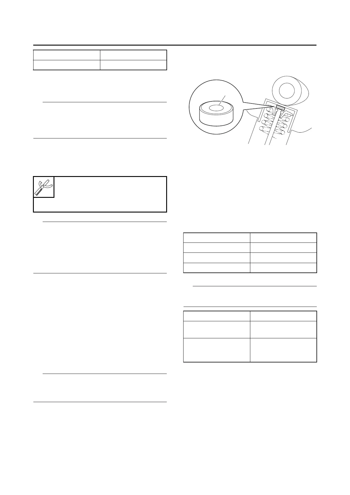
c. Check the thickness of the current valve
pad.
The thickness “a” of each valve pad is marked in
hundredths of millimeters on the side that touch-
es the valve lifter.
Example:
If the valve pad is marked “158”, the pad
thickness is 1.58 mm (0.062 in).
d. Calculate the sum of the values obtained in
steps (b) and (c) to determine the required
valve pad thickness and the valve pad num-
ber.
Example:
1.58 mm (0.062 in) + 0.05 mm (0.002 in) =
1.63 mm (0.064 in)
The valve pad number is 163.
e. Round off the valve pad number according
to the following table, and then select the
suitable valve pad.
Refer to the following table for the available
valve pads.
Example:
Valve pad number = 163
Rounded value = 165
New valve pad number = 165
f. Install the new valve pad and the valve lift-
er.
Cylinder #2 240°
Cylinder #3 480°
Valve lapper (ø14)
90890-04101
Valve lapper (ø14)
YM-A8998
Last digit Rounded value
0, 1, 2 0
3, 4, 5, 6 5
7, 8, 9 10
Valve pad range Nos. 150–240
Valve pad thickness 1.50–2.40 mm
(0.0590–0.0944 in)
Available valve pads 25 thicknesses in
0.05 mm (0.002 in) in-
crements