5-84
CRANKSHAFT AND BALANCER SHAFT
f. Tighten the bolts to specification in the tight-
ening sequence cast on the crankcase. Re-
fer to “CRANKCASE” on page 5-63.
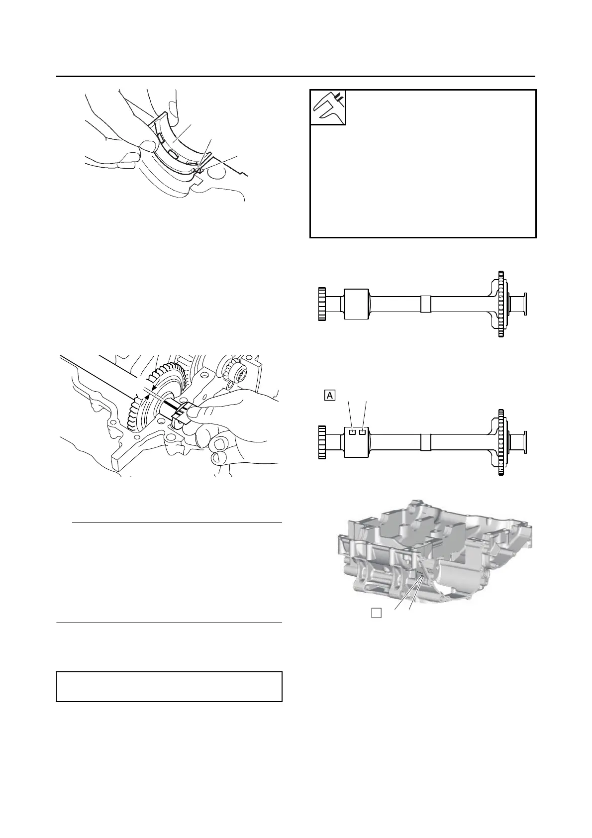
g. Remove the lower crankcase and the bal-
ancer shaft journal lower bearings.
h. Measure the compressed Plastigauge®
width “a” on each balancer shaft journal.
If the balancer shaft-journal-to-balancer
shaft-journal-bearing clearance is out of
specification, select replacement balancer
shaft journal bearings.
4. Select:
• Balancer shaft journal bearing (J
1
–J
2
)
• The numbers “A” stamped into the balancer
shaft web and the numbers “B” stamped into
the lower crankcase are used to determine the
replacement balancer shaft journal bearing siz-
es.
•“J
1
”–“J
2
” refer to the bearings shown in the bal-
ancer shaft and lower crankcase illustration.
For example, if the crankcase “J
1
” and bal-
ancer shaft web “J
1
” numbers are 5 and 2 re-
spectively, then the bearing size for “J
1
” is:
“J
1
” (crankcase) - “J
1
” (balancer shaft web) =
5 - 2 = 3 (brown)
Bearing color code
Code 1
Blue
Code 2
Black
Code 3
Brown
Code 4
Green
Code 5
Yellow