9-90
C0520
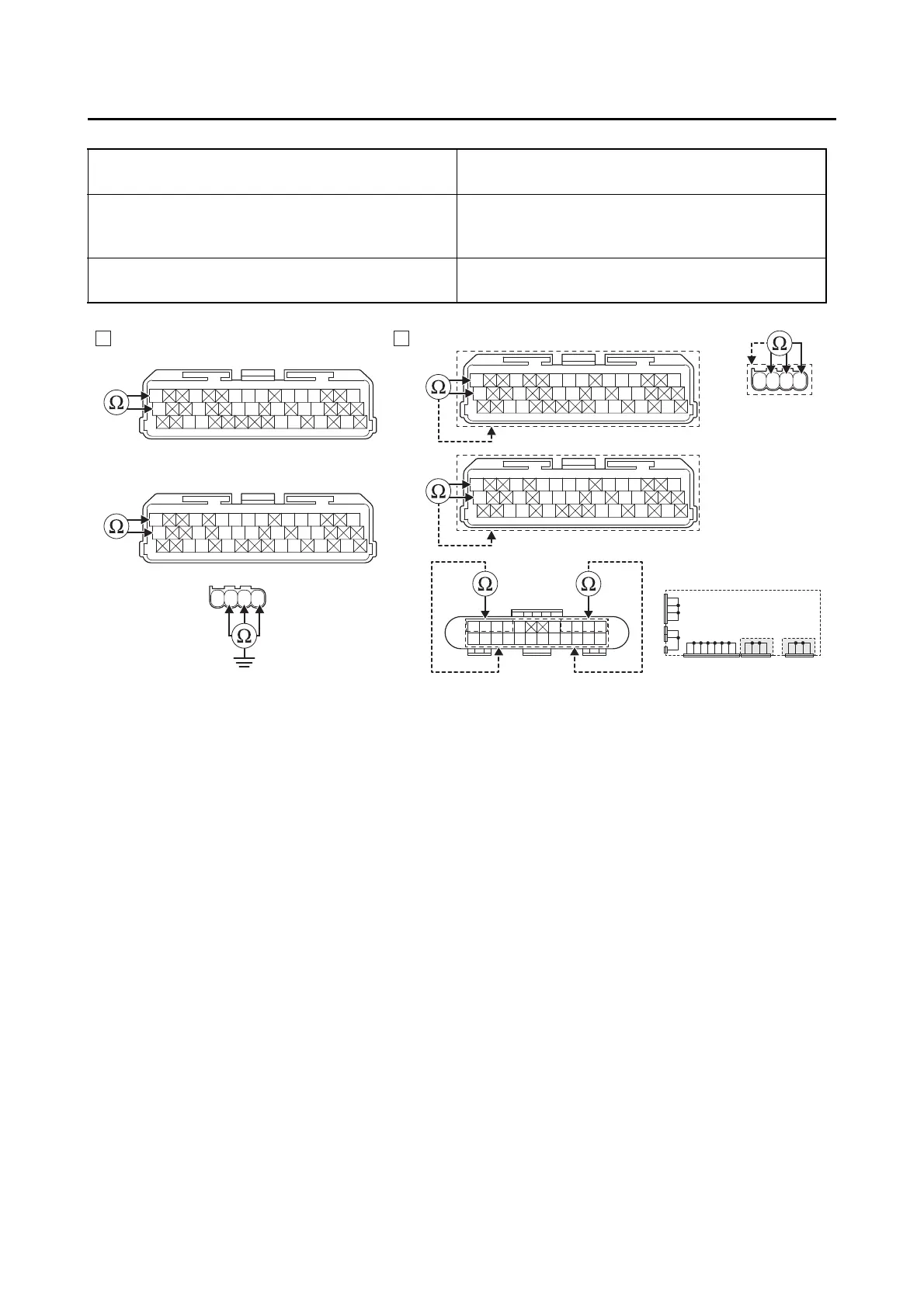
Lines short circuit check “B”
4. Installed condition of IMU.
• Check the installed direction and condition of the sensor.
Refer to “GENERAL CHASSIS (1)” on page 4-1.
• Check the grommet for cracks.
ECU coupler “1”
blue/black–any other coupler terminal
blue/white–any other coupler terminal
IMU coupler “3”
blue/black–any other coupler terminal
blue/white–any other coupler terminal
red/white–any other coupler terminal
Joint coupler “2”
blue/black–any other coupler terminal
blue/white–any other coupler terminal
R/WL/BL/WB/W
R/WL/BL/WB/W
Gy
LLVP
P/WLg/LO/WY/LL/B
B/LB/LBr/WGy/GG/LBr/LB/YL/W
W/YW/GG/WG/WLg/BL/WL/Y
Gy
LLVP
P/WLg/LO/WY/LL/B
B/LB/LBr/WGy/GG/LBr/LB/YL/W
W/YW/GG/WG/WLg/BL/WL/Y
BA
Gy
LLVP
P/WLg/LY/LL/B
B/LB/LBr/WGy/GG/LB/YL/W
W/YW/GG/WG/WL/WL/Y
Gy
LLVP
P/WLg/LY/LL/B
B/LB/LBr/WGy/GG/LB/YL/W
W/YW/GG/WG/WL/WL/Y
L/W
WW
L/W
BB
L/B L/B Y/B Y/B
L/R L/R L/RL/RB/L
B
B/L
BBBBB
1
*
1
**
1
*
1
**
3
3
2
*. MTN890
**. MTN890D
Is resistance ∞ Ω?
YES
→ Go to step 4.
NO
a. Replace the wire harness.
b. Turn the main switch to “ON”, and then check the condition of the DTC using the malfunction
mode of the YDT.
Is it in the “Recovered” condition?
YES
→ Go to step 7, and complete the service.
NO
→ Go to step 4.