9-97
P00D1, P2195
3. Connection of ECU coupler.
• Check the locking condition of the coupler.
• Disconnect the coupler and check the pins (bent or broken terminals and locking condition of the
pins).
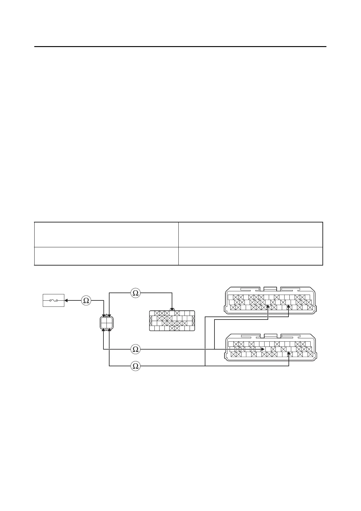
4. Wire harness continuity.
• Disconnect the O
2
sensor coupler “1”, ECU coupler “2” and ignition fuse 1 “3”.
• Open circuit check
Is the coupler condition normal?
YES
→ Go to step 4.
NO
a. Connect the coupler securely or replace the wire harness.
b. Start the engine and let it idle for approximately 1 minute.
c. Check the condition of the DTC using the malfunction mode of the YDT.
Is it in the “Recovered” condition?
YES
→ Go to step 8, and complete the service.
NO
→ Go to step 4.
Between O
2
sensor coupler “1” and ECU cou-
pler “2”
gray/green–gray/green
pink/black–pink/black
black/blue–black/blue
Between O
2
sensor coupler “1” and ignition fuse
1 holder “3”
red–red
2
*
2
**
Gy
LLVP
P/WY/LL/B
B/LB/LBr/WGy/GB/YL/W
W/YW/GG/WG/WL/WL/Y
Gy
LLVP
P/WLg/LO/WY/LL/B
B/LB/LBr/WGy/GG/LBr/LB/YL/W
W/YW/GG/WG/WLg/BL/WL/Y
O
Gy/RO/GP/BY/R
B
R/BG/BL/BLg/R
B
G/YR/L
B/WB/WR/LL/WY/BY/RR/G
R
P/B
Gy/G
B/L
1
2
3
*. MTN890
**. MTN890D
Is resistance 0 Ω?
YES
→ Go to “Short circuit check”.
NO
a. Replace the wire harness.
b. Start the engine and let it idle for approximately 1 minute.
c. Check the condition of the DTC using the malfunction mode of the YDT.
 Loading...


