9-131
P0132
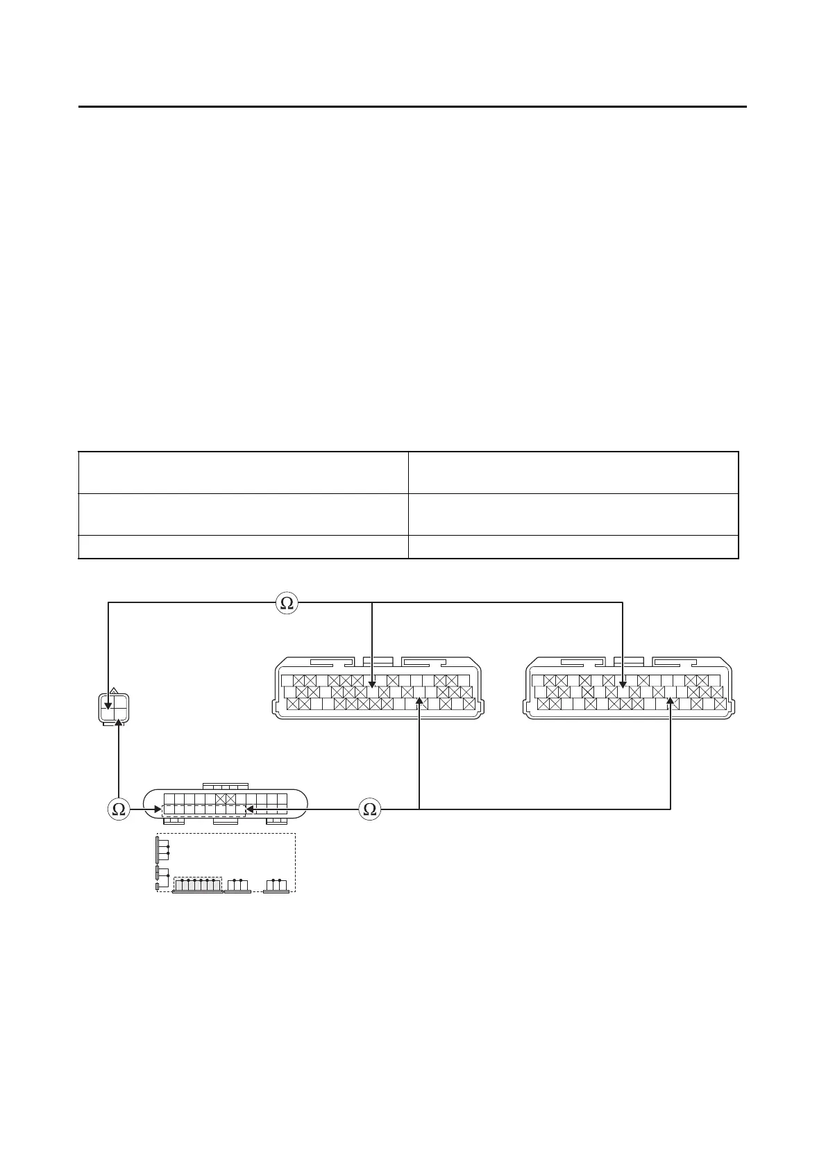
4. Wire harness continuity.
• Disconnect the O
2
sensor coupler “1” and ECU coupler “3”.
• Remove the joint coupler cap “2”.
• Open circuit check
Is the coupler condition normal?
YES
→ Go to step 4.
NO
a. Connect the coupler securely or replace the wire harness.
b. Turn the main switch to “ON”, and then check the condition of the DTC using the malfunction
mode of the YDT.
Is it in the “Recovered” condition?
YES
→ Go to step 7, and complete the service.
NO
→ Go to step 4.
Between O
2
sensor coupler “1” and ECU cou-
pler “3”
gray/green–gray/green
Between O
2
sensor coupler “1” and joint coupler
“2”
black/blue–black/blue
Between joint coupler “2” and ECU coupler “3” black/blue–black/blue
Gy
LLVP
P/WO/WY/LL/B
B/LB/LBr/WGy/GBr/LB/YL/W
W/YW/GG/WG/WLg/BL/WL/Y
R
P/B
Gy/G
B/L
Gy
LLVP
P/WY/LL/B
B/LB/LBr/WGy/GB/YL/W
W/YW/GG/WG/WL/WL/Y
L/W
WW
L/W
BB
L/B L/B Y/B Y/B
L/R L/R L/RL/RB/L
B
B/L
BBBBB
3
**
3
*
2
1
*. MTN890
**. MTN890D
Is resistance 0 Ω?
YES
→ Go to “Short circuit check”.
NO
a. Replace the wire harness.
b. Turn the main switch to “ON”, and then check the condition of the DTC using the malfunction
mode of the YDT.