9-152
P0335
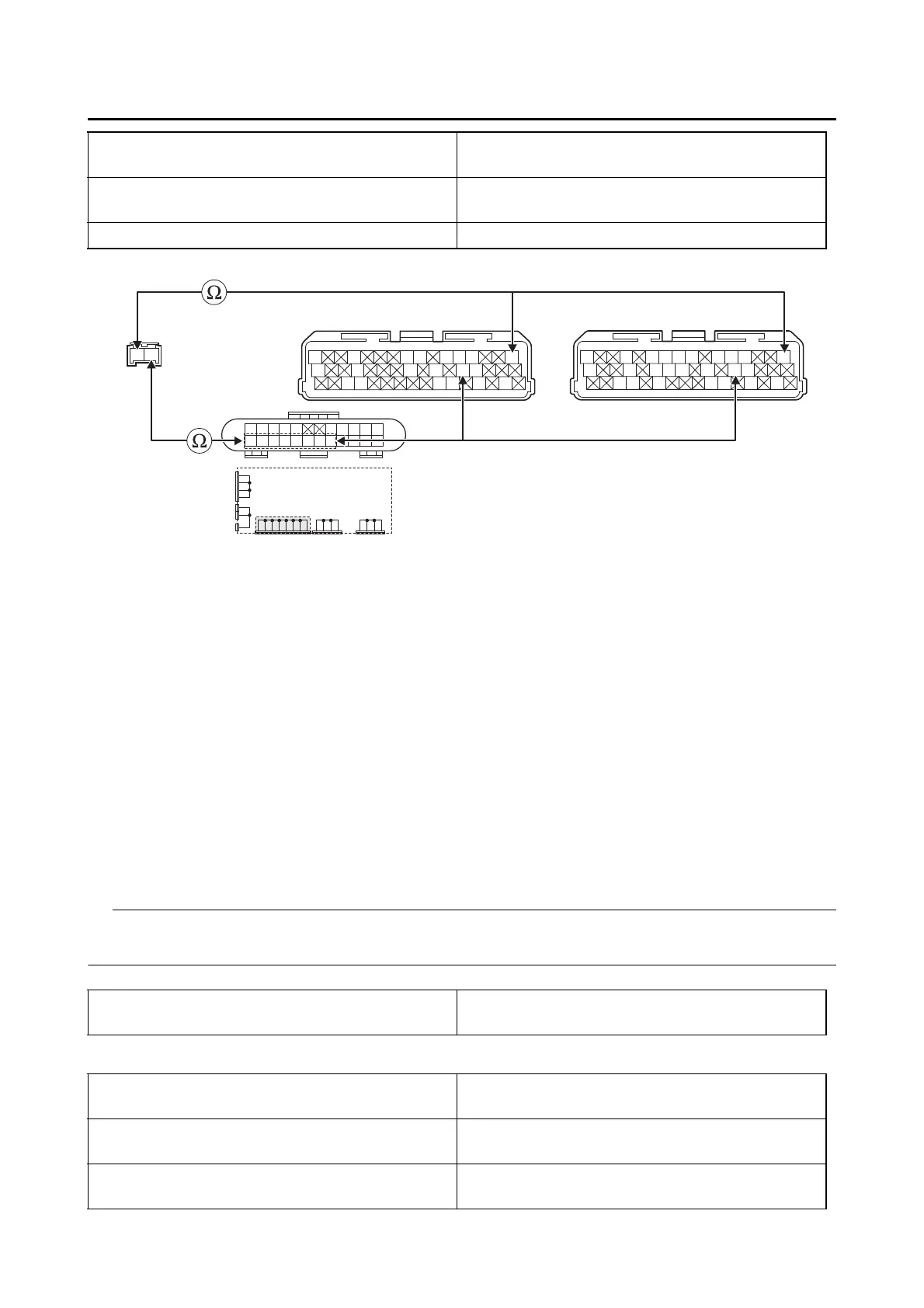
• Short circuit check
Disconnect the ECU related connectors before checking.
Refer to “PARTS CONNECTED TO THE ECU” on page 9-4.
Ground short circuit check “A”
Lines short circuit check “B”
Between crankshaft position sensor coupler “1”
and ECU coupler “3”
gray–gray
Between crankshaft position sensor coupler “1”
and joint coupler “2”
black–black
Between joint coupler “2” and ECU coupler “3” black/blue–black/blue
Gy B
3
*
3
**
Gy
LLVP
P/WY/LL/B
B/LB/LBr/WGy/GB/YL/W
W/YW/GG/WG/WL/WL/Y
Gy
LLVP
P/WLg/LO/WY/LL/B
B/LB/LBr/WGy/GG/LBr/LB/YL/W
W/YW/GG/WG/WLg/BL/WL/Y
L/B
W
L/B L/B L/B
B
L/B L/B L/B L/B
L/B L/B L/BL/RB/L
B
B/L
BBBBB
1
2
*. MTN890
**. MTN890D
Is resistance 0 Ω?
YES
→ Go to “Short circuit check”.
NO
a. Replace the wire harness.
b. Crank the engine, and then check the condition of the DTC using the malfunction mode of the
YDT.
Is it in the “Recovered” condition?
YES
→ Go to step 7, and complete the service.
NO
→ Go to “Short circuit check”.
Between crankshaft position sensor coupler “1”
and ground
gray–ground
Crankshaft position sensor coupler “1”
black/blue–any other coupler terminal
gray–any other coupler terminal
Joint coupler “2”
black–any other coupler terminal
black/blue–any other coupler terminal
ECU coupler “3”
black/blue–any other coupler terminal
gray–any other coupler terminal