9-236
P1606, P1607
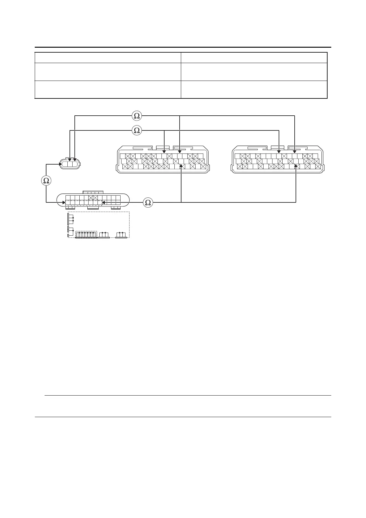
• Short circuit check
Disconnect the ECU related connectors before checking.
Refer to “REPLACING THE ECU (Engine Control Unit)” on page 8-56.
Between ECU coupler “3” and joint coupler “2” [P1607] black/blue–black/blue
Between ECU coupler “3” and intake air pres-
sure sensor 2 coupler “1”
[P1607] blue–blue
[P1606, P1607] pink–pink
Between intake air pressure sensor 2 coupler
“1” and joint coupler “2”
[P1607] black–black
BP L
Gy
LLVP
P/WY/LL/B
B/LB/LBr/WGy/GB/YL/W
W/YW/GG/WG/WL/WL/Y
Gy
LLVP
P/WLg/LO/WY/LL/B
B/LB/LBr/WGy/GG/LBr/LB/YL/W
W/YW/GG/WG/WLg/BL/WL/Y
L/W
WW
L/W
BB
L/B L/B Y/B Y/B
L/R L/R L/RL/RB/L
B
B/L
BBBBB
3
*
3
**
1
2
*. MTN890
**. MTN890D
Is resistance 0 Ω?
YES
→ Go to “Short circuit check”.
NO
a. Replace the wire harness.
b. Turn the main switch to “ON”, and then check the condition of the DTC using the malfunction
mode of the YDT.
Is it in the “Recovered” condition?
YES
→ Go to step 7, and complete the service.
NO
→ Go to “Short circuit check”.