6.5 Speed Control
6.5.1 Basic Settings for Speed Control
6-16
6.5
Speed Control
There are two types of speed control: speed control with an analog voltage reference and
speed control with internal set speeds. This section describes speed control with an analog
voltage reference.
You input a speed reference into the SERVOPACK with an analog voltage to operate the Servo-
motor at the reference speed. Refer to the following section for information on speed control
with internal set speeds.
6.9 Internal Set Speed Control on page 6-53
• If you create a position loop in the host controller, you use the SERVOPACK for speed con-
trol.
• If you need to control only the speed of the Servomotor, you use the SERVOPACK for speed
control.
You set the control method in Pn000 = n.X (Control Method Selection).
Set Pn000 to n.0 to set the control method to speed control.
6.5.1
Basic Settings for Speed Control
This section describes the use of the V-REF (Speed Reference Input) Signal, /SPD-D (Motor
Direction Input) Signal, speed reference input gain, and speed reference offset adjustment in
speed control with analog voltages.
V-REF (Speed Reference Input) Signal
Input the V-REF (Speed Reference Input) signal to the SERVOPACK to operate the Servomotor
at a speed that is proportional to the input voltage.
Maximum input voltage: ±12 VDC
If you will use a host controller, such as a programmable controller, for position control, connect
the above output pins to the speed reference output terminals on the host controller.
Note: Always use twisted-pair cables to control noise.
/SPD-D (Motor Direction Input) Signal
You can turn the /SPD-D signal ON and OFF to change the direction of the Servomotor.
Note: You must allocate the /SPD-D signal to use it. Use Pn50C = n.X (/SPD-D (Motor Direction) Signal Allo-
cation) to allocate the signal to a connector pin. Refer to the following section for details.
6.1.1 Input Signal Allocations on page 6-4
Parameter Meaning When Enabled Classification
Pn000
n.0
(default setting)
Speed control with analog references After restart Setup
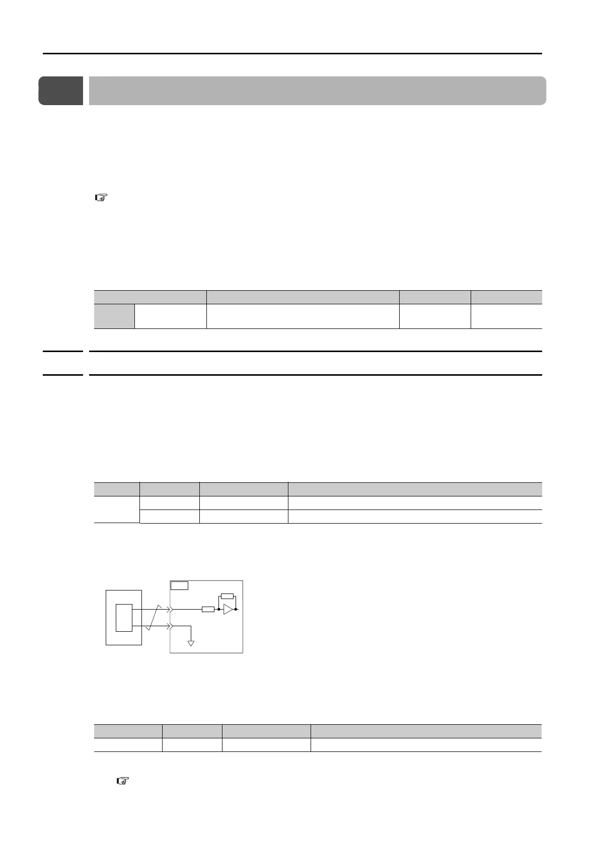
Typ e Signal Connector Pin No. Meaning
Input
V-REF CN1-5 Speed reference input signal
SG CN1-6 Signal ground for speed reference input signal
Classification Signal Connector Pin No. Description
Input /SPD-D Must be allocated. Changes the Servomotor direction.
SG
CN1
6
V-REF
5
D/A
0 V
Host controller
Approx. 14 k
SERVOPACK