6.6 Position Control
6.6.1 Basic Settings for Position Control
6-30
6.6.1
Basic Settings for Position Control
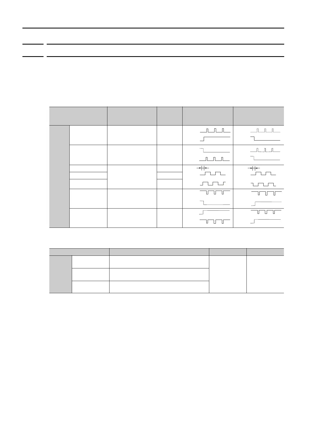
This section describes the reference pulse forms and input filters.
Reference Pulse Forms
To perform speed control, you must specify how the reference is input from the host controller
(i.e., the reference pulse form). You set the reference pulse form in Pn200 (Position Control Ref-
erence Form Selections).
Selecting an Input Filter
Parameter
Reference Pulse
Form
Input
Pulse
Multiplier
Forward Reference Reverse Reference
Pn200
n.
0
(default setting)
Sign and pulse train,
positive logic.
−
n.
1
CW and CCW pulse
trains, positive logic
−
n.2
90° phase-differen-
tial pulses
×1
n.3 ×2
n.
4 ×4
n.
5
Sign and pulse train,
negative logic.
−
n.
6
CW and CCW pulse
trains, negative logic
−
Parameter Meaning When Enabled Classification
Pn200
n.0
(default setting)
Use the reference input filter 1 for a line-
driver signal. (1 Mpps max.)
After restart Setup
n.1
Use the reference input filter for an open-col-
lector signal. (200 kpps max.)
n.2
Use reference input filter 2 for a line-driver
signal. (1 to 4 Mpps)
PULS
(CN1-7)
SIGN
(CN1-11)
High level
PULS
(CN1-7)
SIGN
(CN1-11)
Low level
CW
(CN1-7)
CCW
(CN1-11)
Low level
CW
(CN1-7)
CCW
(CN1-11)
Low level
90
Phase A
Phase B
Phase A
(CN1-7)
Phase B
(CN1-11)
90
°
PULS
(CN1-7)
SIGN
(CN1-11)
Low level
PULS
(CN1-7)
SIGN
(CN1-11)
High level
CW
(CN1-7)
CCW
(CN1-11)
High level
CW
(CN1-7)
CCW
(CN1-11)
High level

 Loading...


