6.3 Troubleshooting Based on the Operation and Conditions of the Servomotor
6-47
Servomotor
Does Not
Start
A failure occurred in the
SERVOPACK.
–
Turn OFF the power
supply to the servo
system.
Replace the SERVO-
PACK.
–
The polarity detection was
not executed.
Check the setting of
Pn080 =n.X (Polar-
ity Sensor Selection).
Correct the parameter
setting.
*
Check the inputs to the
SV_ON (Servo ON) com-
mand.
• If you are using an
incremental linear
encoder, send the
SV_ON command
from the host control-
ler.
• If you are using an
absolute linear
encoder, execute
polarity detection.
*
Servomotor
Moves
Instanta-
neously,
and Then
Stops
There is a mistake in the Ser-
vomotor wiring.
Turn OFF the power sup-
ply to the servo system.
Check the wiring.
Wire the Servomotor
correctly.
–
There is a mistake in the wir-
ing of the encoder or Serial
Converter Unit.
Turn OFF the power sup-
ply to the servo system.
Check the wiring.
Wire the Serial Con-
verter Unit correctly.
–
There is a mistake in the lin-
ear encoder wiring.
Turn OFF the power sup-
ply to the servo system.
Check the wiring.
Wire the cable cor-
rectly.
–
The setting of Pn282 (Linear
Encoder Scale Pitch) is not
correct.
Check the setting of
Pn282.
Correct the setting of
Pn282.
*
The count-up direction of the
linear encoder does not
match the forward direction
of the Moving Coil in the
motor.
Check the directions.
Change the setting of
Pn080 = n.X
(Motor Phase
Sequence Selection).
Place the linear
encoder and motor in
the same direction.
*
Polarity detection was not
performed correctly.
Check to see if electrical
angle 2 (electrical angle
from polarity origin) at any
position is between ±10°.
Correct the settings for
the polarity detection-
related parameters.
–
Servomotor
Speed Is
Unstable
There is a faulty connection
in the Servomotor wiring.
The connector connec-
tions for the power line
(U, V, and W phases) and
the encoder or Serial
Converter Unit may be
unstable.
Turn OFF the power sup-
ply to the servo system.
Check the wiring.
Tighten any loose ter-
minals or connectors
and correct the wiring.
–
Continued on next page.
Continued from previous page.
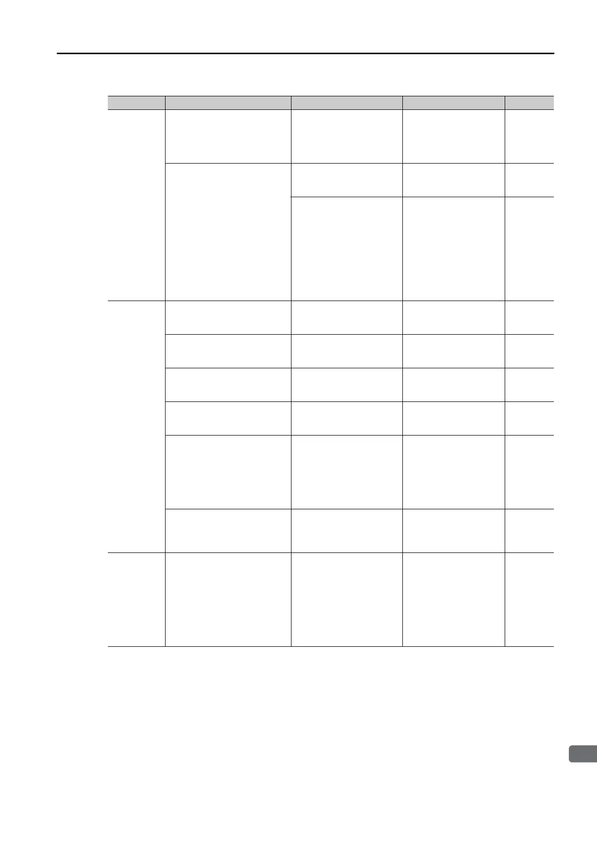
Problem Possible Cause Confirmation Correction Reference

 Loading...


