6-42
IM AQ6370D-01EN
Integrated Power Markers
Integrated power markers show integrated power values over specified frequency ranges
by assuming the marker position on the waveform to be the center. The power values are
displayed in the data area. These markers are used to determine the integrated power of
a widely spread spectrum such as to determine the signal level from a modulated optical
signal spectrum. The selectable range of frequency to integrate over is ±1.0 to ±999.9
GHz. If you press the COARSE key, you can set the value in 10 GHz steps using the
rotary knob or arrow keys. If you do not press the COARSE key, you can set the value in
1 GHz steps.
To determine the signal level of a modulated optical signal, set the integration frequency
range so that the point approximately –30 dB below the spectrum peak is included.
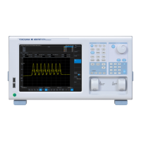
The waveform in the integration range appears highlighted (in blue).
The way to move the markers and the data display between markers are the same as
with the above-mentioned moving markers.
Advanced marker type: INTG (integrated power marker)
Integrated power marker power values
Note
When advanced markers are in use, the marker levels at the end of measurements are
automatically updated.
6.9 Marker Display

 Loading...


