App-29
IM AQ6370D-01EN
Appendix
App
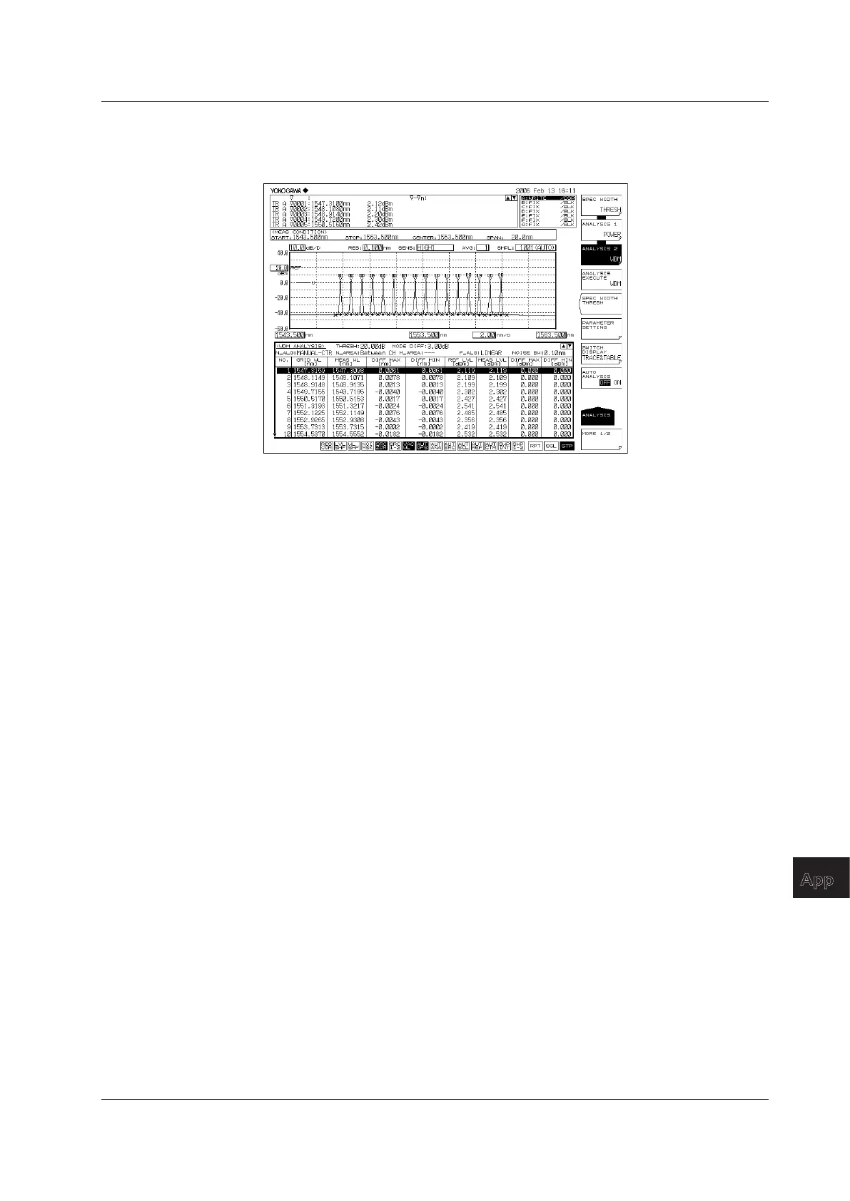
DRIFT(GRID)
Grid wavelengths are used as references to display wavelength/level changes (drifts).
Note that reference levels are previous measurement levels.
Explanations of display items
NO: Channel number
GRID WL: Reference wavelength of the channel (grid wavelength)
MEAS WL: Center wavelength of the channel
DIFF MAX (wavelength): Maximum value of the relative wavelength to the reference
wavelength of the channel
DIFF MIN (wavelength): Minimum value of the relative wavelength to the reference
wavelength of the channel
REF LVL: Reference level of the channel (previous measurement level)
MEAS WL: Measurement level of the channel
DIFF MAX (level): Maximum value of the relative level to the reference level of the
channel
DIFF MIN (level): Minimum value of the relative level to the reference level of the
channel
• Absolute values and reference values to the GRID table are displayed. The GRID
table can be freely configured.
• Reference wavelengths/levels can be changed under the following conditions:
• When MAX/MIN RESET is set by the parameter, reset is performed by the active
trace waveform data.
• Reset is performed by the first waveform data that was measured when wavelength
axes (SPAN WL/START WL/STOP WL) were changed by measurement conditions.
Appendix 4 Detailed Explanations of WDM Analysis Function

 Loading...


