Maintenance, Troubleshooting, & Technical Specifications 3 - 11
Cradle Signal Descriptions
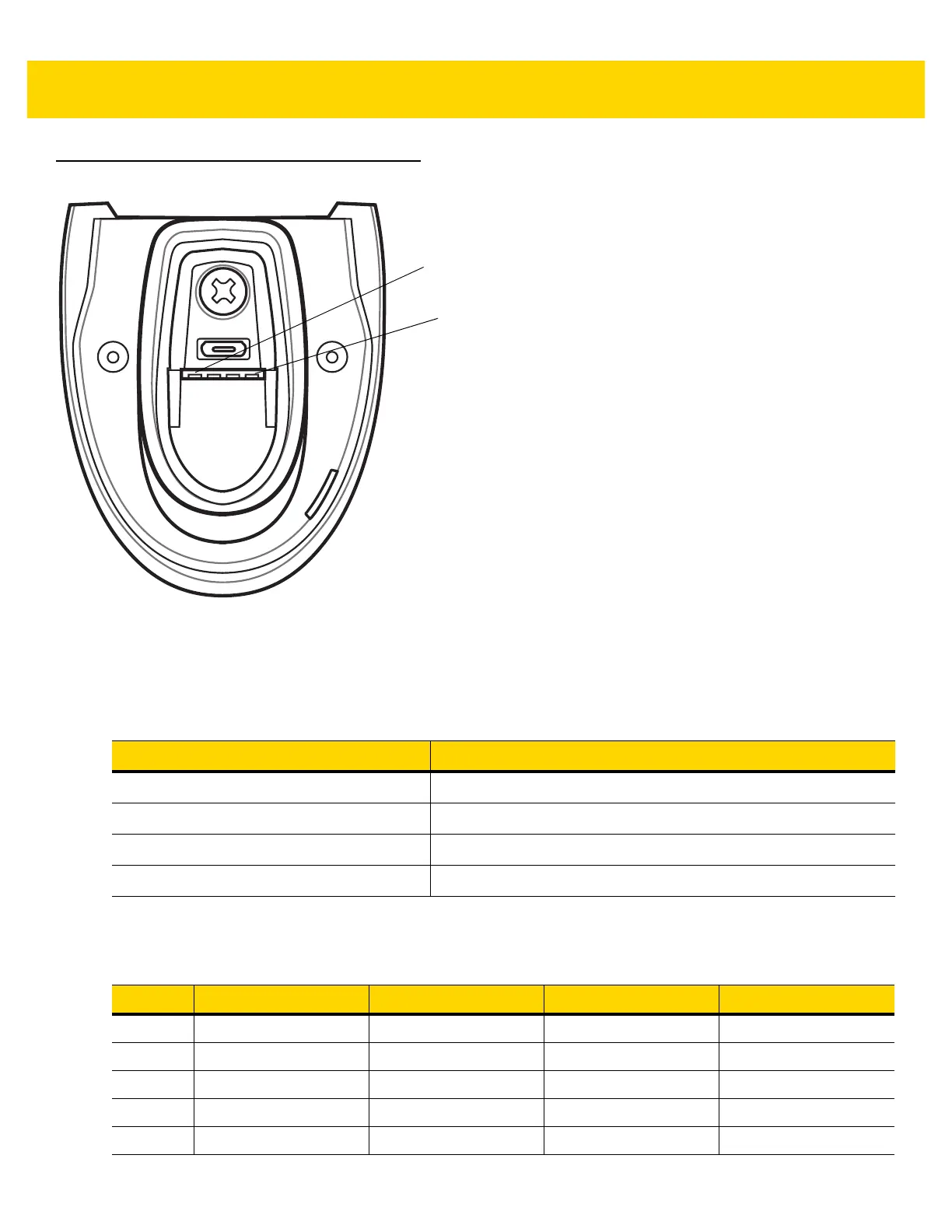
Figure 3-1 Cradle Pinouts
The signal descriptions in Table 3-3 apply to the contacts on the digital scanner and are for reference only.
The signal descriptions in Table 3-4 apply to the connectors on the DS2278 digital scanner and are for reference
only.
Table 3-3 Signal Pinouts
Pin Function
15VDC
2 USB_D-
3USB_D+
4 Ground
Table 3-4 DS2278 Digital Scanner Signal Pin-outs
Pin USB RS-232 Keyboard Wedge IBM
1 Short to Pin 6 Reserved 1M Resistor to Pin 8 2M Resistor to Pin 8
2 Power Power Power Power
3 Ground Ground Ground Ground
4 Reserved TXD KBD_CLK IBM_TXD
5 D + RXD TERM_DATA IBM_RXD
 Loading...