Installation and Maintenance Manual - Aastra 5000 AMT/PTD/PBX/0058/4/6/EN
Maintenance 01/2011 Page 415
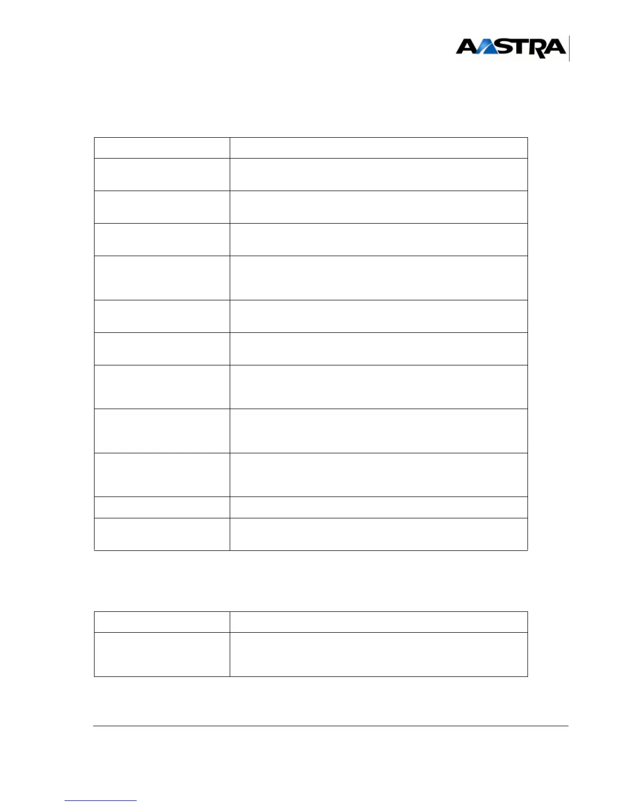
Table 4:
OPERATION DETAILS OF THE OPERATION / COMMENTS
• Unscrew the two securing
screws on the mains unit.
• Disconnect the fan cable
from the power supply.
• Pull out the power supply
module.
• Unscrew the power supply module and pull it out slowly.
• Check the functional
technical state of the new
power supply module.
• Check that the functional technical state of the new power supply
module is compatible with the old one.
• Fit the new power supply
module.
• Insert the power supply module in its slot and secure it with its
screws.
• Connect the fan cable to
the power supply.
• Screw on the mains unit
(at the back of the
cabinet).
• Connect the power supply
ribbon cable to the CPU
card.
• Mount the expansion
ribbon cable holder
(AXS).
•
• Refit the backplane. • Connect the backplane to the main card.
• If required, connect the
expansion ribbon cable.
• If the iPBX has two cabinets, connect the expansion ribbon cable
linking the back plane to the expansion cable connector.
Table 5:
OPERATION DETAILS OF THE OPERATION / COMMENTS
• Reinstall the expansion
cards.
• Place the guide rails.
• Insert the card in its slot and lock it in place using the 1/4 turn
locks (see Section 4.1).