Installation and Maintenance Manual - Aastra 5000 AMT/PTD/PBX/0058/4/6/EN
Maintenance 01/2011 Page 437
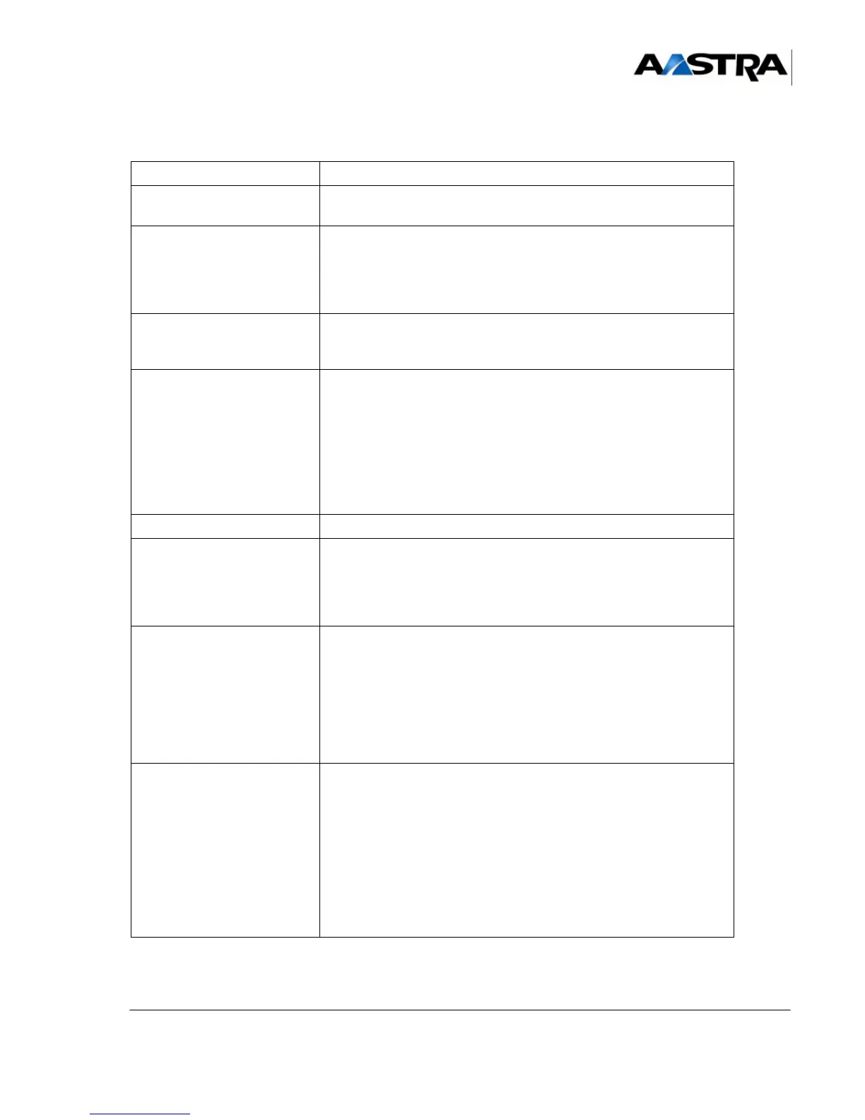
• Install the module.
i-Button.
• Install the i-button module of the old IUCV-D card on the new
card.
• Remove and recover the
i-button
identification number.
• Remove and recover, at the back of the cabinet, the label with
the i-Button's identifier number (the i-Button's identifier label
only, not the product identification label).
• Stick the i-Button's identification label on the back of the new
cabinet.
• Recover the expansion
cards from the old
cabinet.
• Install the cards in the
new cabinet.
Expansion cards and new UCV-D card(s).
Nota : Since UCV-D card(s) may be fitted with
daughter cards, check that the new card(s) is/are
equipped exactly like the previous one(s), except in
case of modification its/their configuration(s) owing
to a change in its/their capacity(capacities) (in this
case, see Section 4.3 or the product “Data sheet”).
• Fit the new cabinet.
• Install the cables exactly
like in the old cabinet.
• On the front panel of the expansion cards
• On the front panel of the IUCV-D card
• On the front panel of the UCV-D card(s)
• If the iPBX has an expansion cabinet, at the back of the cabinet
• On the front panel of the power supply module.
• Connect the mains cable • Connect one end of the mains cable to the power supply module
of the cabinet and the other end to a grounded mains power
point.
Attention : The iPBX must be powered off when installing
the mains cable.
Never connect network lines while the mains
power cable is unplugged.
• Power on the iPBX. • Before powering on the cabinet, check that all the following tasks
have been performed:
- all line connections are installed,
- all equipment has been connected to a grounded power point.
• Power on the iPBX:
- for an iPBX with several cabinets, first power on the expansion
cabinet by setting the “I/O” switch of the power supply module(s)
to position “I”.
- Set the “I/O” switch on the main cabinet power supply module(s)
to “I”.
• Check the status of the indicators (see Sections 4.3 to 4.7).
Table 18:
OPERATION DETAILS OF THE OPERATION / COMMENTS
 Loading...


