Pole discordance signal from circuit breaker
+
circuit breaker
en05000287.vsd
IEC05000287 V2 EN-US
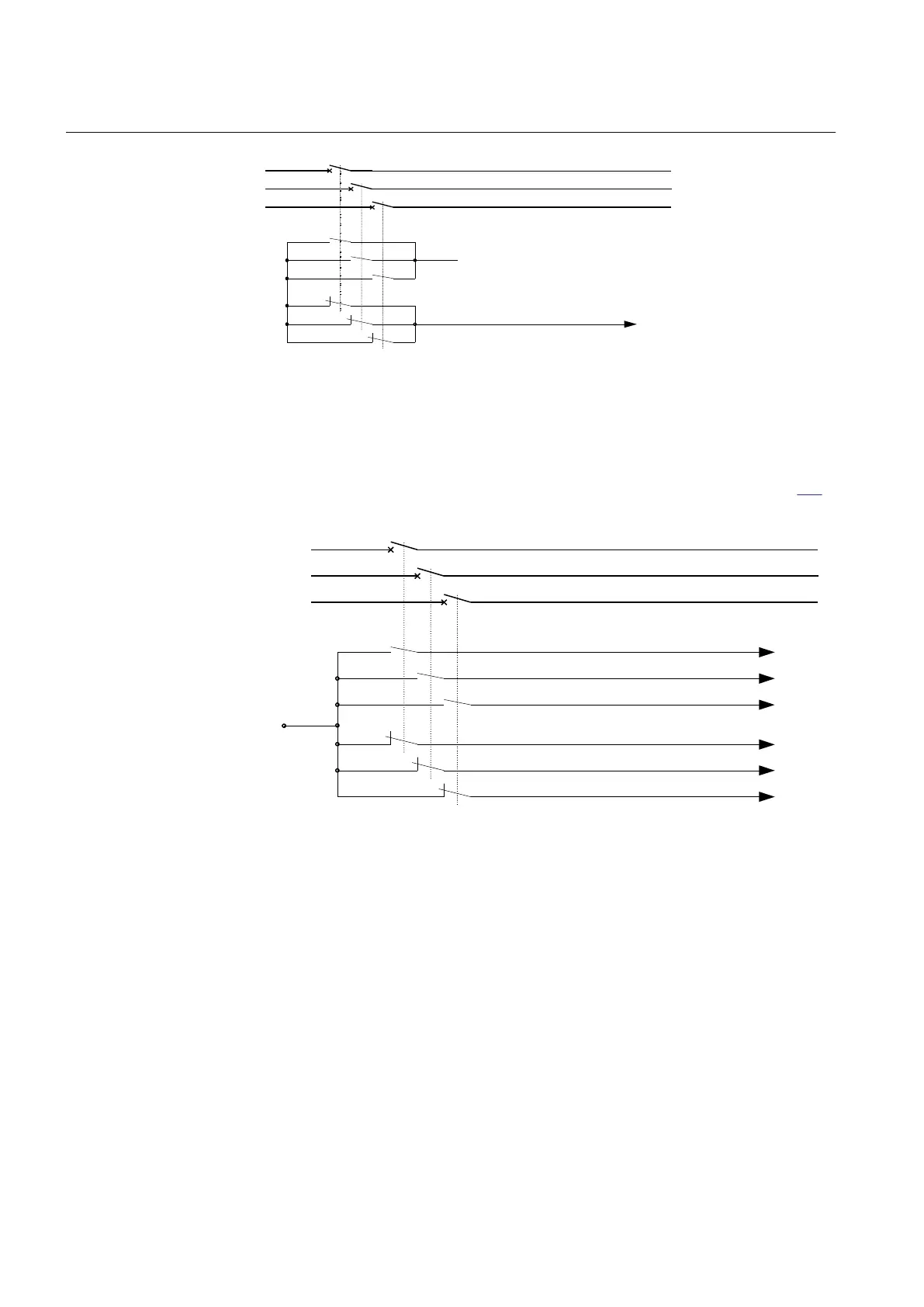
Figure 118: Pole discordance external detection logic
This binary signal is connected to a binary input of the IED. The appearance of this
signal will start a timer that will give a trip signal after the set time delay.
There is also a possibility to connect all phase selective auxiliary contacts (phase
contact open and phase contact closed) to binary inputs of the IED, see figure
119.
poleTwoOpened from C.B.
+
C.B.
poleOneOpened from C.B.
poleThreeClosed from C.B.
poleTwoClosed from C.B.
poleOneClosed from C.B.
poleThreeOpened from C.B.
en05000288.vsd
IEC05000288 V1 EN-US
Figure 119: Pole discordance signals for internal logic
In this case the logic is realized within the function. If the inputs are indicating pole
discordance the trip timer is started. This timer will give a trip signal after the set
delay.
Pole discordance can also be detected by means of phase selective current
measurement. The sampled analog phase currents are pre-processed in a discrete
Fourier filter (DFT) block. From the fundamental frequency components of each
phase current the RMS value of each phase current is derived. The smallest and the
largest phase current are derived. If the smallest phase current is lower than the
setting CurrUnsymLevel times the largest phase current the settable trip timer
(tTrip) is started. The tTrip timer gives a trip signal after the set delay. The TRIP
signal is a pulse 150 ms long. The current based pole discordance function can be
Section 7 1MRK 506 382-UEN A
Current protection
248 Line distance protection REL650 2.2 IEC
Technical manual