120 | XSE RIES G5 | 21060 2 6MN AA
10.7.5 Replace or add communication modules (COMM modules)
The XSeries
G5
devices support two serial communication interfaces. Communication modules are
required to activate those interfaces. Each can be configured as either RS-232 or RS-485. Standard
configuration may ship with a COMM1 module already installed. Use this procedure to replace or add
new communication modules. When adding new modules, make sure you order the type required by
the external equipment you plan to connect to the COMM terminals.
WARNING – Bodily injury. Attach a ground strap to your body and connect it to a good
earth ground before handling any electronic boards. This discharges any electrical static
buildup in your body to the ground, instead of to the electronic board.
IMPORTANT NOTE: If replacing a module with a module of a different type, rewiring will
be required. For RS-485 communication, set the termination jumper based on the number
of external devices you plan to connect.
10.7.5.1 Before you replace or add modules
To prepare to replace/add modules:
Connect with the device using PCCU entry mode.
Follow the procedures to backup device data and configuration as described in section 10.1
Preserve data and configuration.
Verify that the lithium battery backup is enabled, and that the lithium battery voltage level
is OK:
a. View the scrolling parameters on the LCD. Verify that the Lithium Backup parameter
displays Yes. If it displays No, enable the lithium battery backup.
b. Verify that the LL battery alarm does not display on the LCD. Or, measure the lithium
battery to verify that it registers more than 3.0 V. If the lithium battery is low, replace
the lithium battery first according to section 10.7.2 Replace the lithium battery.
Open the enclosure door.
Disconnect the power source as described in section 10.5.1 Remove power from the
electronic board.
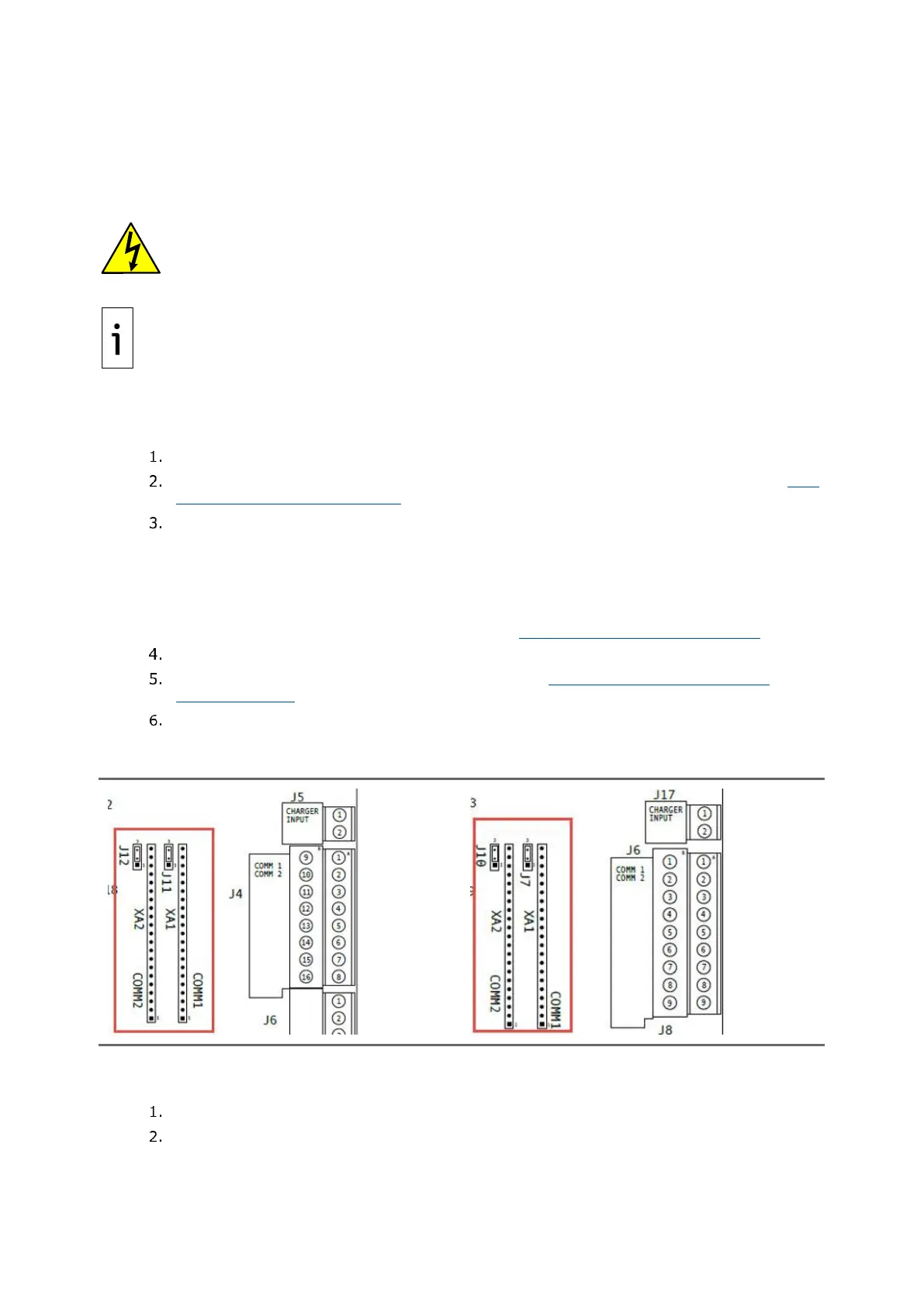
Locate the COMM modules or slots [COMM1 (XA1) and COMM2 (XA2)] located left of the
COMM terminal ports on the right side of the electronic board.
Figure 10-26: XFC
G5
COMM ports
Figure 10-27: XRC
G5
COMM ports
10.7.5.2 Remove modules
Remove the communication modules from the COMM1 (XA1) and COMM2 (XA2) slots.
Identify the module to be replaced.
Grasp firmly in the middle of the module and gently pull straight out to avoid bending or
breaking the module pins.

 Loading...