21060 26M N AA | X SER IE S
G5
| 33
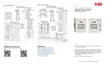
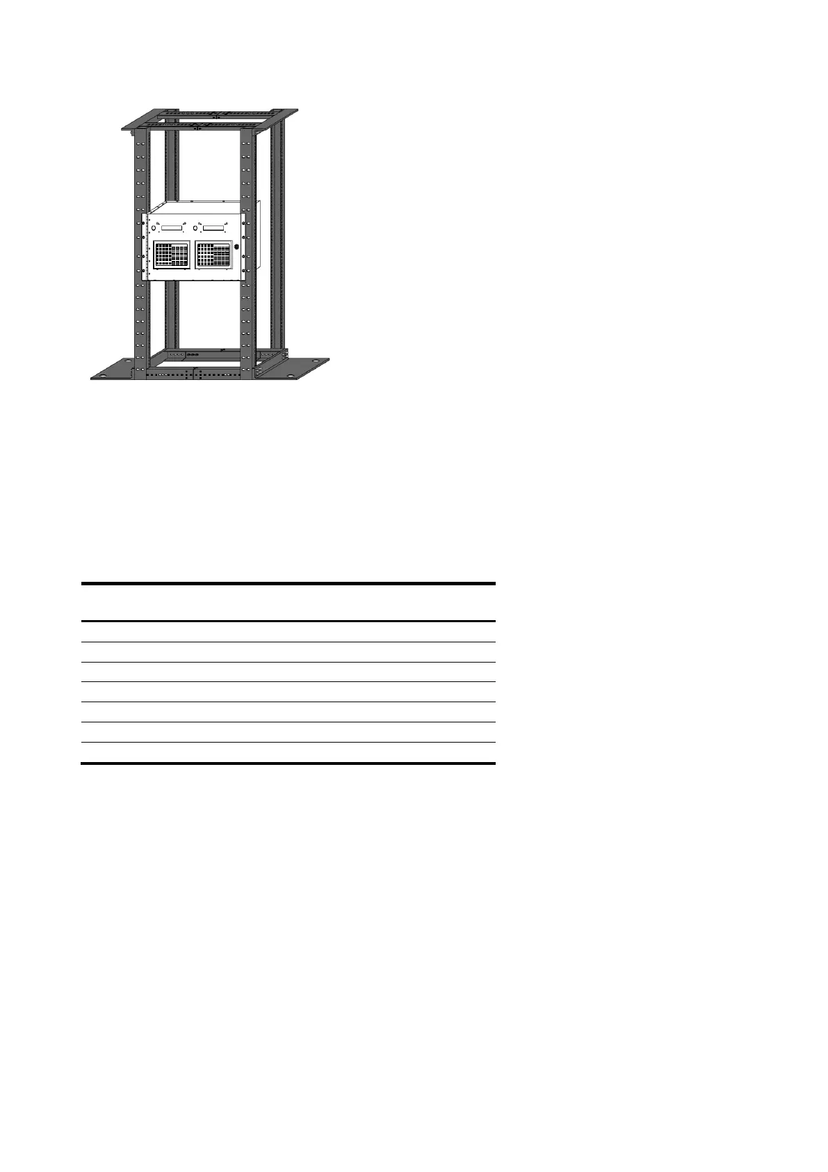
Figure 3-3:XRC
G5
6990 rack mount
3.7.2 Termination panel
User connections to the XRC
G5
6990 are made on the termination panel on the rear of the enclosure.
No internal wiring connections should have to be made by the user. Two termination panels are
available, depending upon whether the user ordered a single XRC
G5
6990 or a Dual Unit with two
XRC
G5
controller boards.
Terminal designations on the back panel are identical to designated pin outs on the XRC
G5
main
electronic board(s). Any wiring instruction (WI) or User Drawing (UD) applicable to the XRC
G5
will be
applicable to the XRC
G5
6990 but wired to the corresponding plug on the rear of the enclosure. Table
10 shows XRC
G5
jumper/termination panel correlation.
Table 3-1: XRC
G5
Main electronic board to termination panel correlation chart
3.7.3 Rack mount enclosure
The XRC
G5
6990 enclosure is designed for 19” rack mount. This enclosure may be configured to house
up to two XRC
G5
boards, up to two LCD displays and up to two optional key pads. This unit is not
designed for exposure to the elements.
Except for the local PCCU connector, all terminals are located on the back panel of the enclosure.

 Loading...