36 | XSE RI ES G5 | 210602 6MNAA
WARNING: Bodily injury. Install electrical wiring according to requirements for the area
classification. Refer to the certification drawing indicated on the device’s name tag, and national
and local codes.
IMPORTANT NOTE: This procedure applies to the XFC
G5
only. The XRC
G5
does not have onboard
support for RTD inputs.
Materials:
RTD probe with cable and cable gland installed (probe and cable length determined by
technician)
Nylon tie wraps
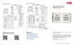
Install the RTD probe:
Insert the RTD probe into the thermowell to determine the depth setting for the probe
spring.
Figure 3-6: Typical RTD installation
Use snap-ring pliers to adjust the retaining ring below the spring on the probe. Probe depth
should be set so it is spring-loaded against the bottom of the thermowell.
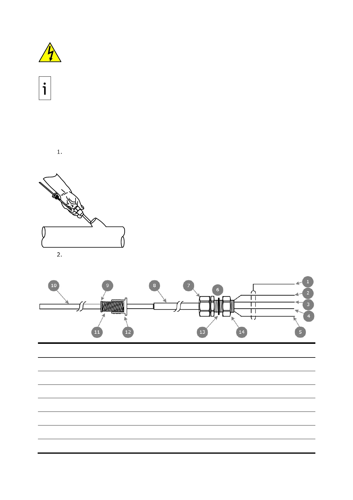
Figure 3-7: RTD probe connector
Legend: RTD Probe Connector
SHLD (Drain wire= Green wire)

 Loading...