EasyManuals Logo

ABB X Series User Manual

ABB X Series
145 pages
To Next Page IconTo Next Page
To Previous Page IconTo Previous Page
Page #52 background imageLoading...
Page #52 background image
52 | XSE RI ES G5 | 210602 6MNAA
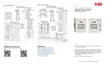
Figure 6-2: XRC AI terminals and input mode selector jumpers
Table 6-5: XRC AI Pinouts
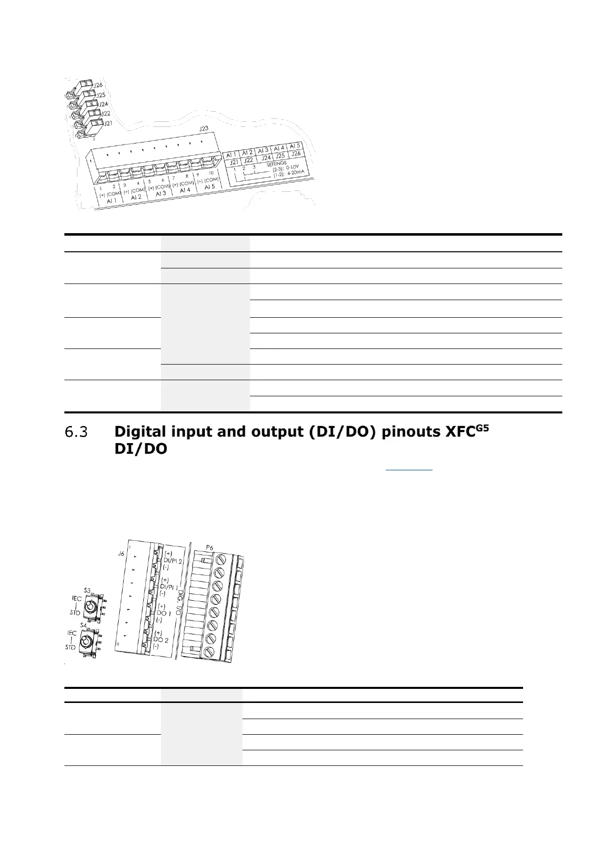
Input
Pin
Description
AI-1
1
(+) Input signal
2
(COM) Input ground
AI-2
3
(+) Input signal
4
(COM) Input ground
AI-3
5
(+) Input signal
6
(COM) Input ground
AI-4
7
(+) Input signal
8
(COM) Input ground
AI-5
9
(+) Input signal
10
(COM) Input ground
The XFC
G5
has 2 onboard digital outputs and 2 onboard digital inputs. Figure 6-3 shows the Digital I/O
terminals on the XFC
G5
and the input mode switches. The input mode switches support standard pulse
inputs (STD) or pulse inputs from Coriolis (IEC). Remember to set the switch to the correct position
based on the type of pulse input signal expected. Use S3 for DI/PI 1 or S4 for DI/PI 2.
Listed below are the DIs and DOs for the XFC
G5
.
Figure 6-3: XFC
G5
DI/PI/DO terminals and input mode switches
Table 6-6: XFC
G5
DI/PI/DO pinouts
I/O
Pin J6
Description
DI2/PI2
1
(+) Input signal
2
(-) Input ground
DI1/PI1
3
(+) Input signal
4
(-) Input ground

Table of Contents

Other manuals for ABB X Series

Questions and Answers:

Question and Answer IconNeed help?

Do you have a question about the ABB X Series and is the answer not in the manual?

ABB X Series Specifications

General IconGeneral
BrandABB
ModelX Series
CategoryMeasuring Instruments
LanguageEnglish

Related product manuals