21060 26M N AA | X SER IE S
G5
| 47
*Blank cells carry no signal.
IMPORTANT NOTE: If wiring for RS-485 communication, set the termination jumpers (J11 or
J12) in the correct position.
To wire equipment to the XRC
G5
serial communication ports, determine the port, insert the correct
communication module type in the available slot, then refer to the generic wiring diagram or pinout
table.
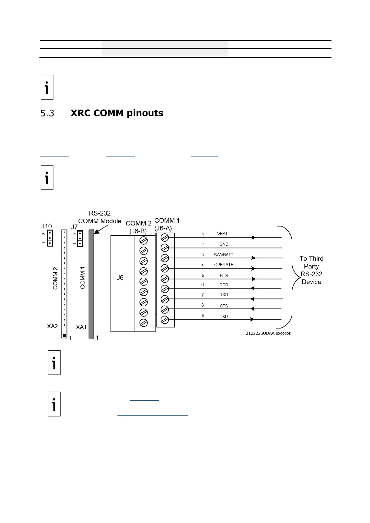
COMM 1 and COMM 2 have identical pinouts. Use J6-A to wire COMM1 or J6-B to wire COMM2. See
Figure 5-5 (RS 232) or Figure 5-6 (RS 485). Refer to Table 5-4 for complete pinout for both ports.
IMPORTANT NOTE: Wiring for RS-485 communication, set the termination jumpers (J7 or J10). in the correct position. See ).
Figure 5-5: XRC RS-232 COMM 1
IMPORTANT NOTE: Typically, only TXD, RXD and GND may be required to communicate
with a third-party RS-232 device. The figure above illustrates all lines associated with the
COMM1 or COMM2 RS-232 module.
IMPORTANT NOTE: Figure 5-6 (RS 485 COMM1) shows connection lines to a single device.
RS-485 supports multiple devices per port. For additional wiring options, search additional
user drawings at www.abb.com/upstream.

 Loading...