21060 26M N AA | X SER I E S
G5
| 121
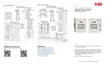
10.7.5.3 Insert modules
Insert the communication modules into the COMM1 (XA1) and COMM2 (XA2) slots:
Remove modules from their package.
Grasp each new module in the middle and align the pins with the slot. Module pin 1
(indicated by a dot mark on the flat side of the module) must connect to slot pin 1
indicated on the board.
Gently insert the module straight into the slot to avoid bending or breaking the module
pins.
For RS-485, set the termination jump correctly.
Wire the COMM port based on the COMM module type. If a module has been replaced with
a module of a different type, make sure to rewire the terminal connector to the match the
type.
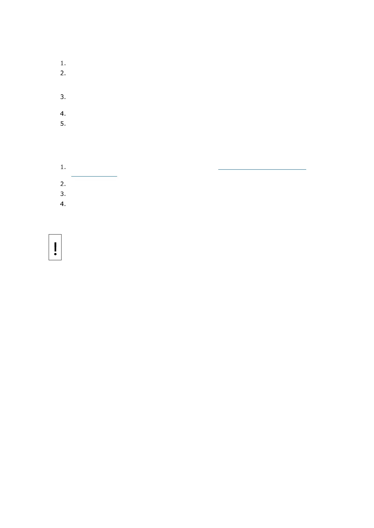
10.7.5.4 Restore power to the board
After module insertion is complete:
Restore power to the board as described in section 10.5.2 Reconnect power to the
electronic board.
Verify startup sequence is completed.
Close the enclosure door.
Verify COMM connections. If new equipment has been added. Review the wiring and
startup procedures in this manual.
10.7.6 Replace the transducer (XFC
G5
only)
NOTICE – Equipment damage: The external power/charger and battery connections must
be removed before removing all other cables, boards, and field connections. Connecting or
disconnecting cables and wires on the electronic board while power is applied can damage
the electronic components.

 Loading...