7352 Series Digital Multimeter Operation Manual
4.1.2 Rear Panel Description
4-6
4.1.2 Rear Panel Description
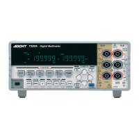
Figure 4-3 Rear Panel (7352A)
1. Power connector Connector for the AC power supply
The included power cable is connected here.
2. Fuse holder assembly The power supply voltage can be selected from 100 V, 120 V, 220
V, and 240 V. A slow-blow fuse is stored here.
3. USB connector Connector for USB
This connector is used to output data and for remote control.
4. GPIB connector (7352A) Connector for GPIB
This connector is used to output data and for remote control.
5. RS-232 connector (7352A) Connector for RS-232
This connector is used to output data and for remote control.
6. TRIGGER IN (7352A) This connector is used to input the external trigger.
7. Current input terminal protection fuse
Protects the current input terminal (Ach).
8. Measurement input terminals TEMP HI and LO terminals
A thermocouple for measuring temperature is connected here.