7352 Series Digital Multimeter Operation Manual
4.2.1 Measurement Functions
4-11
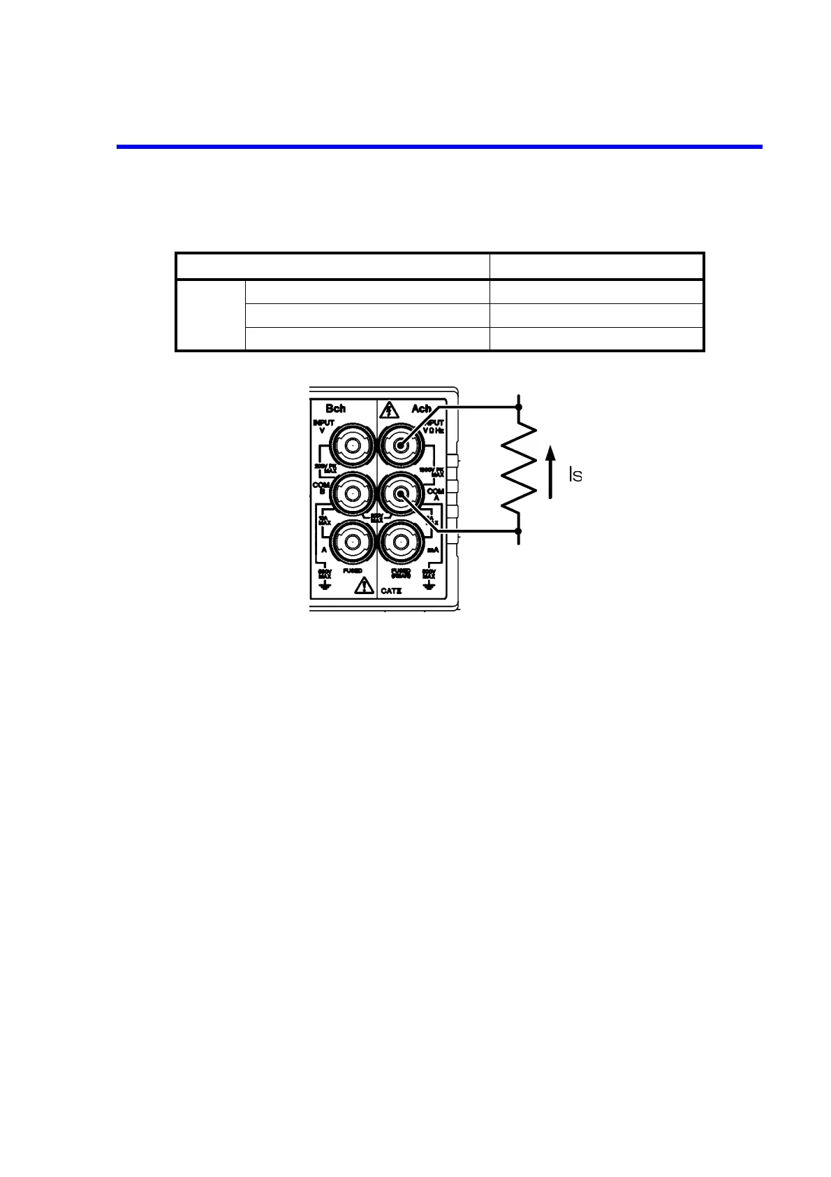
Figure 4-7 Resistance Measurement (2W-Ach and LP-2W-Ach)
The measurement result includes the input cable resistance and contact resistance. To reject these re-
sistance effects, short the tip of the input cable and set the NULL calculation to ON before the mea-
surement.
Ensure the following when in the high-resistance measurement to reduce the effect of the induction
noise.
• Shielding the DUT.
• Using the A01001 input cable (sold separately) whose HI side is shielded.
• Securing the input cable to prevent movement.
Table 4-4 Maximum Allowable Applied Voltage (2W-Ach, LP-2W-Ach)
Input terminal Maximum allowable applied voltage
Ach
Between VHz and COM A terminals 1000 Vpeak
Between COM A terminal and the chassis 500 V
Between COM A and COM B terminals 200 V