7352 Series Digital Multimeter Operation Manual
4.2.1 Measurement Functions
4-14
Measurement method TrueRMS
Input range 5% or more of a full scale
Crest factor 3 (However, this value is limited by the current protection fuse rating.)
Filter response time Approx. 1 sec (Time until the measurement value reaches to within
0.1% of the final value)
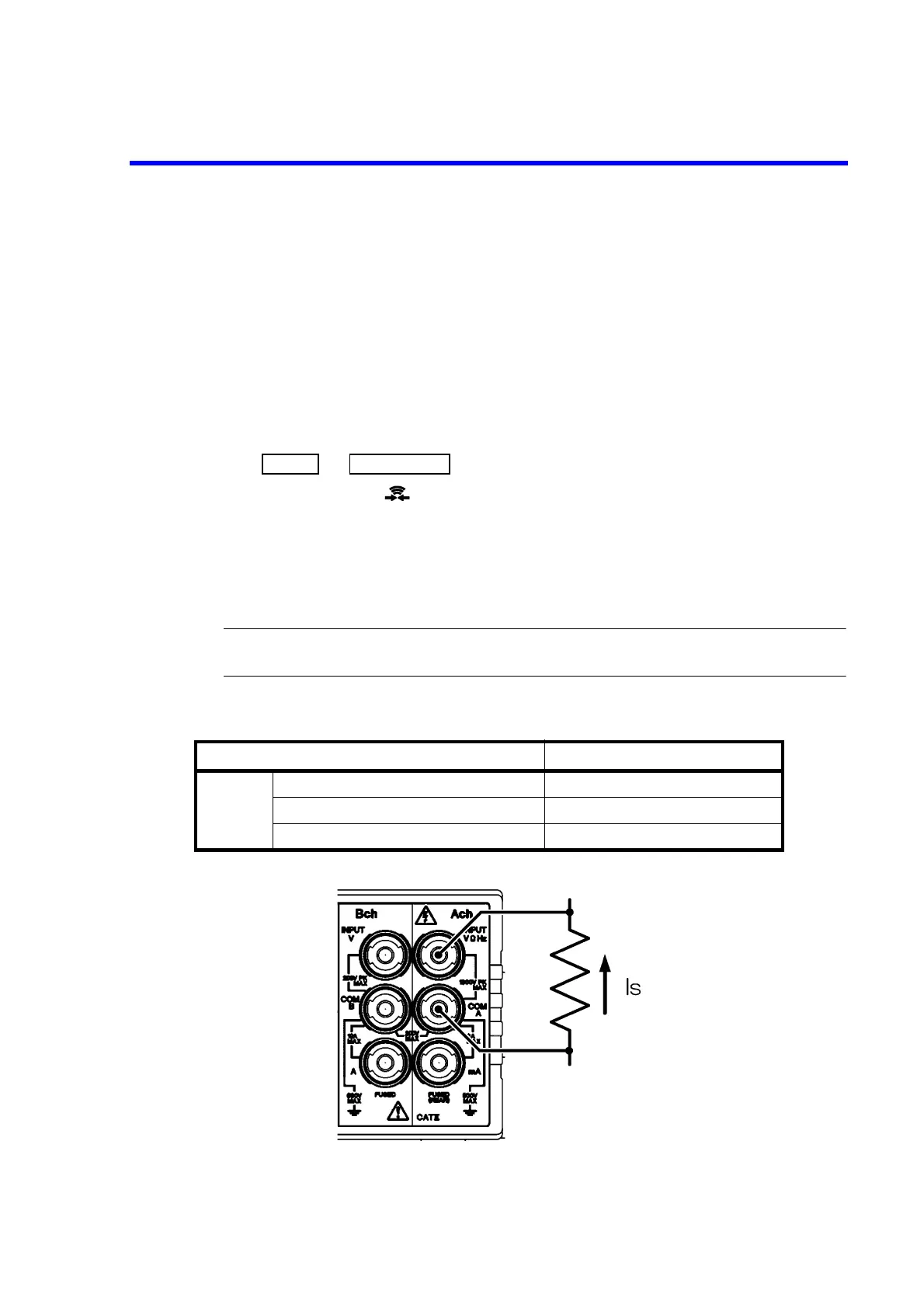
4.2.1.6 Ach Continuity Measurement
1. Connect a DUT to the Ach and COM terminals on the front panel.
2. Press and .
The continuity indicator ( ) is activated.
The resistance is measured using the two wire method. If the measured value is equal to the continuity
threshold constant or less, the buzzer sounds.
Measurement range 2000
Measurement current 1 mA
Continuity threshold constant 1 to 1000
WARNING: Do not apply voltage that exceeds the maximum allowable applied voltage. Fire or electrical
shock due to the failure of this instrument may occur.
Figure 4-10 Continuity Measurement-Ach
Table 4-7 Maximum Allowable Applied Voltage (Continuity-Ach)
Input terminal Maximum allowable applied voltage
Ach
Between VHz and COM A terminals 1000 Vpeak
Between COM A terminal and the chassis 500 V
Between COM A and COM B terminals 200 V