7352 Series Digital Multimeter Operation Manual
4.2.1 Measurement Functions
4-21
Measurement method TrueRMS
Input range 5% or more of a full scale
Crest factor 3 (However, this value is limited by the current protection fuse rating.)
Filter response time Approx. 1 sec (Time until the measurement value reaches to within
0.1% of the final value)
Restrictions on the auto-range
The 10 A range is a fixed range.
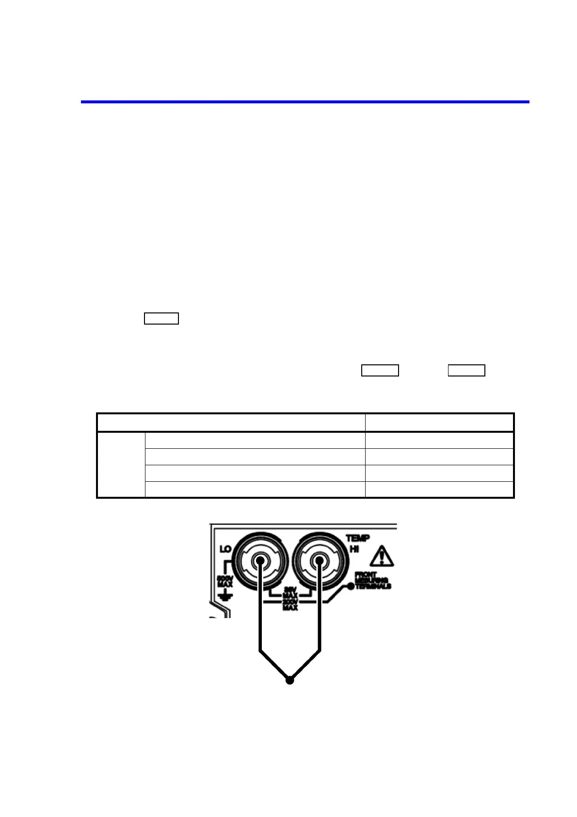
4.2.1.12 Temperature Measurement
Connect a thermocouple to the TEMP HI and LO terminals on the rear panel.
Press .
The ‘C’ indicator is activated.
Temperatures at the terminals are internally compensated.
For the thermocouple, select K or T type from ‘TEMP’ in the category of .
Figure 4-16 Temperature Measurement
Table 4-14 Maximum Allowable Applied Voltage (TEMP)
Input terminal Maximum allowable applied voltage
TEMP
Between TEMP HI and TEMP LO terminals 36 Vpeak
Between TEMP HI/LO terminals and the chassis 500 V
Between TEMP HI/LO terminals and COM A terminal 200 V
Between TEMP HI/LO terminals and COM B terminal 200 V