Description of Connectors on Robot Interface Panel
Adept Viper s650/s850 Robot with MB-60R User’s Guide, Rev D 27
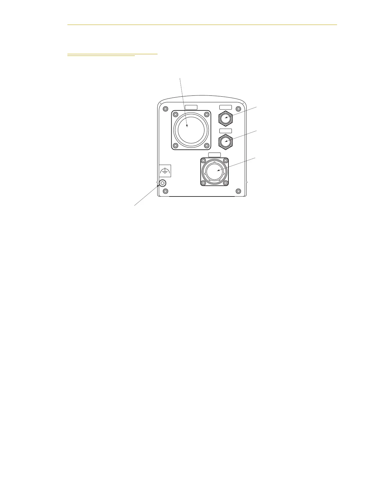
2.6 Description of Connectors on Robot Interface Panel
Figure 2-7. Robot Interface Panel
CN22 - the Arm Power/Signal cable from the MB-60R is installed at this connector.
CN20 - pins 1 to 10 are wired directly to corresponding pins 1 to 10 on CN21 on the upper
arm. Pins 12 to 18 are for solenoid control. See Section 2.7 on page 28.
AIR 1 - air line connector (BSPT1/4) for three solenoids in robot. See Section 2.7 on
page 28.
AIR 2 - air line connector (BSPT1/4), connects directly to AIR 2 on the second (upper)
arm.
Grounding Terminal - protective earth ground point on the robot, see Section 2.5 on
page 26.
CN22
CN20
AIR1
AIR2
Grounding terminal (M5)
CN22 Power/Signal Cable - to MB-60R
CN20
AIR 1
AIR 2