Transporting the Robot
Adept Viper s650/s850 Robot with MB-60R User’s Guide, Rev D 25
Mounting the Robot
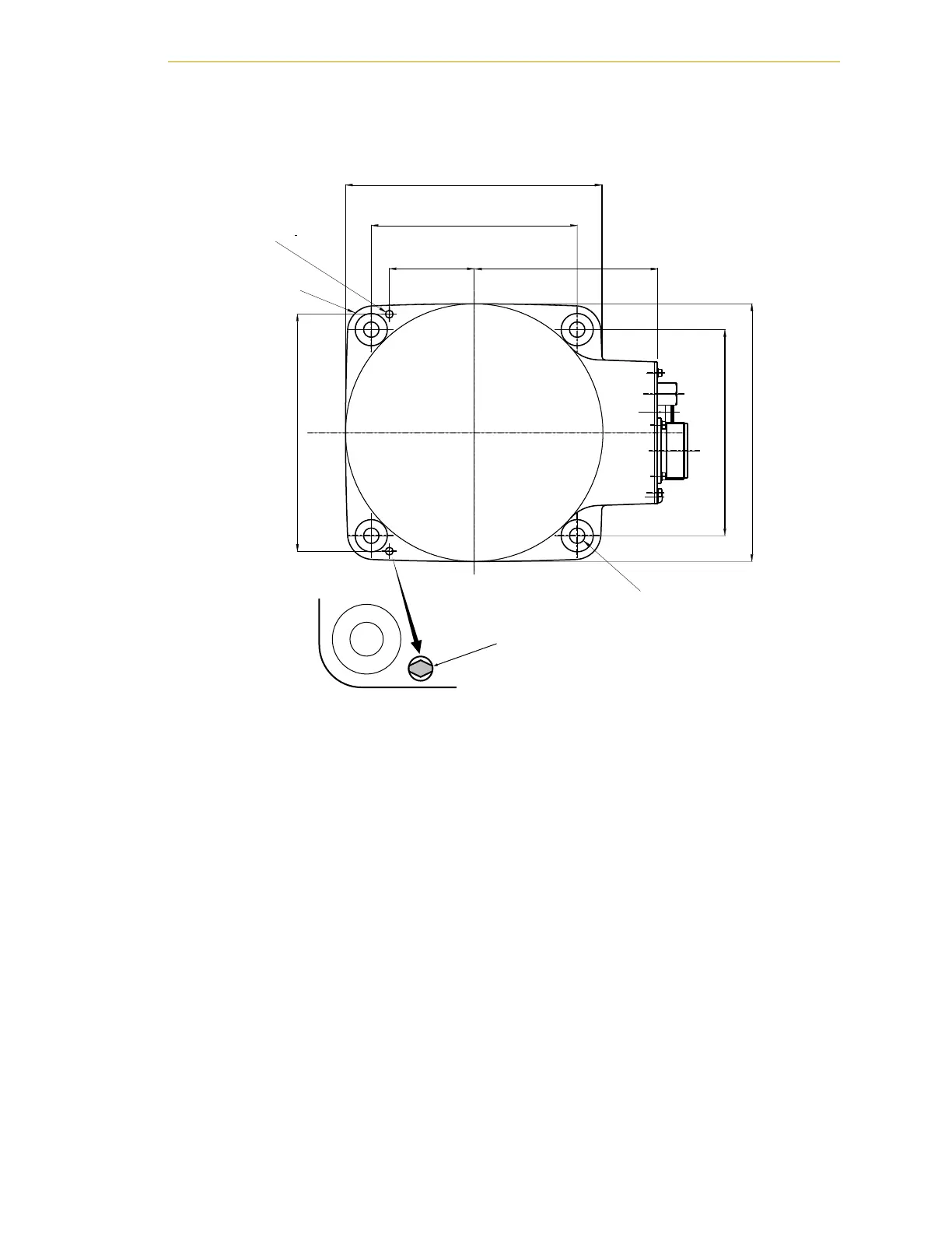
Figure 2-5. Mounting Hole Pattern for Robot
1. See the preceding figure for the dimensions of the mounting holes in the robot
mounting position where the robot is to be secured.
• Drill four bolt holes (M10), 20 mm deep or more.
• Drill a dowel pin hole Ø6, H7 for the diamond shaped pin, 10 mm deep or
more.
• Drill a dowel pin hole Ø6, H7 for the internally threaded positioning pin,
10 mm deep or more.
2. Locate two alignment pins, one round and one diamond-shaped, supplied in the
accessory kit.
3. Drive the diamond-shaped pin into one Ø6, H7 hole so that it is oriented as
shown in Figure 2-5.
4. Drive the internally threaded alignment pin into the other Ø6, H7 hole.
NOTE: Be sure to use the alignment pins. It can minimize positional
deviations that may be caused by the removal/installation of the robot
for maintenance and reduce vibration during operation.
1
R2
.
142.
12 THR
For M1
4
.
160
200
+
.
12
iamond-sha
ed
in