Air Lines and Signal Wiring
Adept Viper s650/s850 Robot with MB-60R User’s Guide, Rev D 89
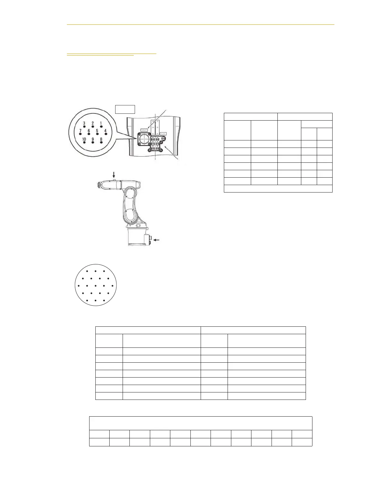
9.3 Air Lines and Signal Wiring
The Cleanroom robot is equipped with six air lines. The six lines, from Valve In input, are
controlled by the three internal solenoid valves. There are ten user electric lines. The air
lines and signal wiring are shown in the following figure.
Table 9-3. CN 20 Pin Assignments, M to U
NPN type (source IN, sink OUT) PNP type (sink IN, source OUT)
CN20 pin
No. Used for:
CN20 pin
No. Used for:
M +24V M0V
N Solenoid 1A (solenoid valve 1) N Solenoid 1A (solenoid valve 1)
P Solenoid 1B (solenoid valve 1) P Solenoid 1B (solenoid valve 1)
R Solenoid 2A (solenoid valve 2) R Solenoid 2A (solenoid valve 2)
S Solenoid 2B (solenoid valve 2) S Solenoid 2B (solenoid valve 2)
T Solenoid 3A (solenoid valve 3) T Solenoid 3A (solenoid valve 3)
U Solenoid 3B (solenoid valve 3) U Solenoid 3B (solenoid valve 3)
Table 9-4. CN 20 Pin Assignments, A to K
Pins A to K on CN20 and #1 to #10 on CN21 are connected with each other as shown below. The
allowable current per line is 1 A.
CN20ABCDEFGHJ K
CN2112345678 910
CN21 pin layout
View A
Solenoid Ports (M5)
CN 20 pin layout
Connector (CN21)
for end-effector control
signal wires
A
CN20, see
robot connector
panel figure
for view.
LMA
KUNB
JTVPC
HSRD
GF E
Table 9-2. Air Intake/Exhaust States
Air Connections Valve Signal
Air Intake
(Valve In)
Exhaust
(Valve
Out)
Solenoid
valve
Solenoid
AB
1A 1B 1 ON OFF
1B 1A 1 OFF ON
2A 2B 2 ON OFF
2B 2A 2 OFF ON
3A 3B 3 ON OFF
3B 3A 3 OFF ON
AIR 2 - Not used on Cleanroom Robot