Adept Viper s650/s850 Robot with MB-60R User’s Guide, Rev D 51
System Installation 4
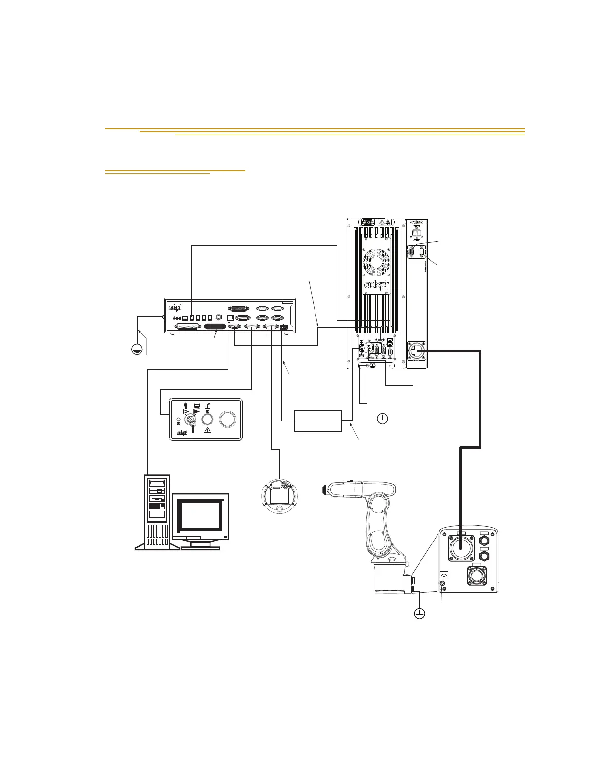
4.1 System Cable Diagram
Figure 4-1. System Cable Diagram for Adept SmartController Robots
NOTE: See “Installing the 24 VDC Cable” on page 56 for additional
system grounding information.
CN22
CN20
AIR1
AIR2
Adept Viper s650
Robot
User-Supplied
Ground Wire
Grounding
Terminal (M5)
Ethernet to PC
IEEE 1394 Cable
from Controller SmartServo (Port 1.1)
to MB-60R SmartServo (Port 1)
Adept MB-60R
Servo Controller
Adept
SmartController CX
User-Supplied
Power Supply
Controller (XFP) to
Front Panel (XFP)
Front Panel
T2 Pendant
(optional)
XSYS Cable
from Controller (XSYS)
to MB-60R (XSLV)
24 VDC Power from
User-Supplied
Power Supply to
Controller (XDC1)
Desktop or Laptop PC
(user-supplied)
Running Adept ACE
Terminator
Installed
User-Supplied Ground Wire
External Brake
Connector
Arm Power/
Signal Cable
24 VDC Power from
User-Supplied
Power Supply to
MB-60R (+24 VDC Input)
User-Supplied
200-240 VAC,
single phase
EXPIO
Connector
NOTE: Objects are
not drawn to scale.
User-Supplied
Ground Wire
STOP
R
R
ON
SmartServo IEEE-1394
1 2 3 4
SF ES HD
SW1
1.1 1.2 2.1 2.2
OK
123
XDIO
LANHPE
OFF
XSYS
CAMERA
Eth 10/100
XUSR
Device Net
XFP
RS-232/TERM
RS-232-1
XMCP
BELT ENCODER
SmartController CX
-+ -+
RS-422/485
XDC1 XDC2
24V 5A
*S/N 3562-XXXXX*
RS-232-2