Robot Flange Dimensions
Adept Viper s650/s850 Robot with MB-60R User’s Guide, Rev D 81
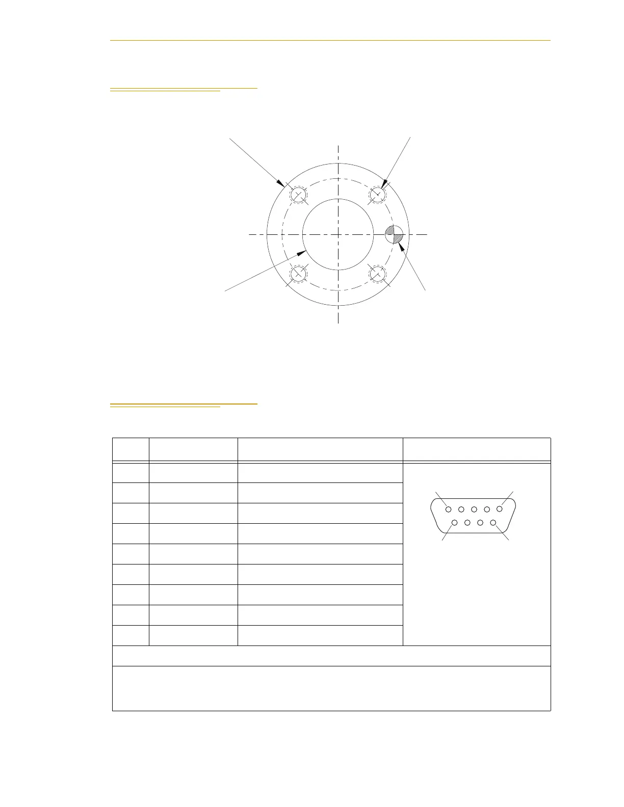
7.2 Robot Flange Dimensions
Figure 7-5. Robot Flange Dimensions
7.3 XSLV Connector
Table 7-1. XSLV Connector Pinout
Pin # Description Comment Pin Location
1 ESTOPGND ESTOP System Ground
XSLV1/2 Connector
as viewed on MB-60R
2 MAN1 ESTOP Manual Input Ch 1
3 MAN2 ESTOP Manual Input Ch 2
4HIPWRDIS High Power Disable
5 ESTOP_RESET Normally Closed Check Contacts
6 AUTO1 ESTOP Auto Input Ch 1
7 AUTO2 ESTOP Auto Input Ch 2
8 N/C
9 ESTOP_SRC ESTOP System +24 V
Mating Connector:
AMP/Tyco #747904-2, 9-pin D-Sub
AMP/Tyco #748676-1, D-Sub Cable Clamp
Ø40 H8
Ø20 H7
6 Deep
4X M5 x 0.08
8 Deep
(31.5 B.C.)
Ø5 H7
7 Deep
0
- 0.039
+ 0.021
0
+ 0.012
0
Pin 1
Pin 5
Pin 6
Pin 9