Chapter 3 - MotionBlox-60R
40 Adept Viper s650/s850 Robot with MB-60R User’s Guide, Rev D
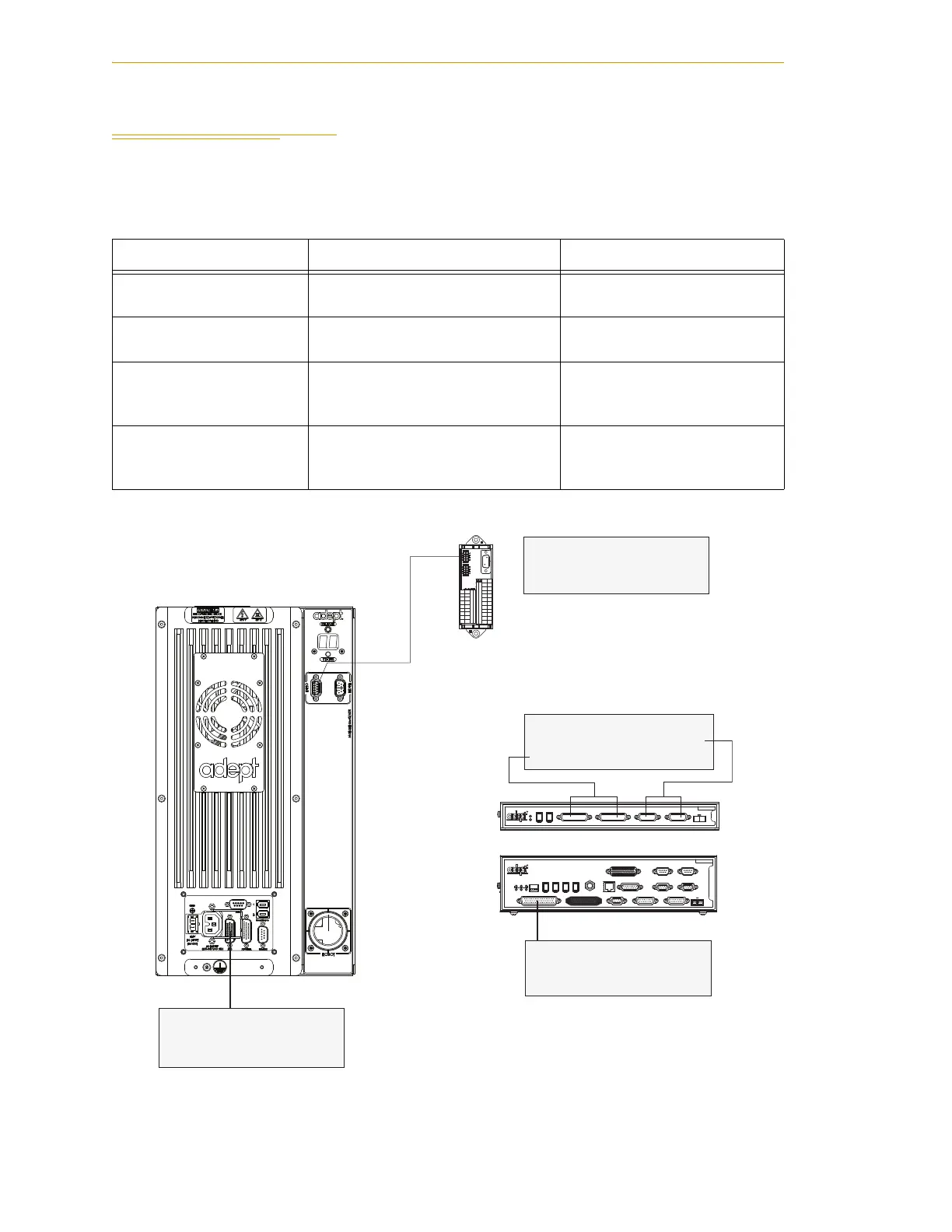
3.4 Connecting Digital I/O to the System
You can connect digital I/O to the system in several different ways. See the following
table and figure.
Figure 3-4. Connecting Digital I/O to the System
Table 3-4. Digital I/O Connection Options
Product I/O Capacity For more details
XIO Connector on
MB-60R
12 inputs
8 outputs
see Section 3.5 on page 42
XDIO Connector on
SmartController
12 inputs
8 outputs
see Adept SmartController
User’s Guide
Optional IO Blox Devices,
connect to EXPIO
connector on the MB-60R
8 inputs, 8 outputs per device; up
to four IO Blox devices per system
see Adept IO Blox User’s
Guide
Optional sDIO Module,
connects to controller
32 inputs, 32 outputs per module;
up to four sDIO devices per
system
see Adept SmartController
User’s Guide
SF
IEEE-1394
X2
SC-DIO
LINK
*S/N 3563-XXXXX*
X1
24V 0.5A
R
OK
X4
- + - +
1.1 1.2
XDC1 XDC2
X3
R
ON
SmartServo IEEE-1394
1 2 3 4
SF ES HD
SW1
1.1 1.2 2.1 2.2
OK
123
XDIO
LANHPE
OFF
XSYS
CAMERA
Eth 10/100
XUSR
Device Net
XFP
RS-232/TERM
RS-232-1
XMCP
BELT ENCODER
SmartController CX
-+ -+
RS-422/485
XDC1 XDC2
24V 5A
*S/N 3562-XXXXX*
RS-232-2
Optional
sDIO #1
SmartController
MB-60R
Optional
IO Blox Device
XIO Connector
12 Input signals: 1097 to 1108
8 Output signals: 0097 to 0104
XDIO Connector
12 Input signals: 1001 to 1012
8 Output signals: 0001 to 0008
IO Blox #1
8 Input signals: 1113 to 1120
8 Output signals: 0105 to 0112
sDIO #1
32 Input signals: 1033 to 1064
32 Output signals: 0033 to 0064