Chapter 5 - System Operation
66 Adept Viper s650/s850 Robot with MB-60R User’s Guide, Rev D
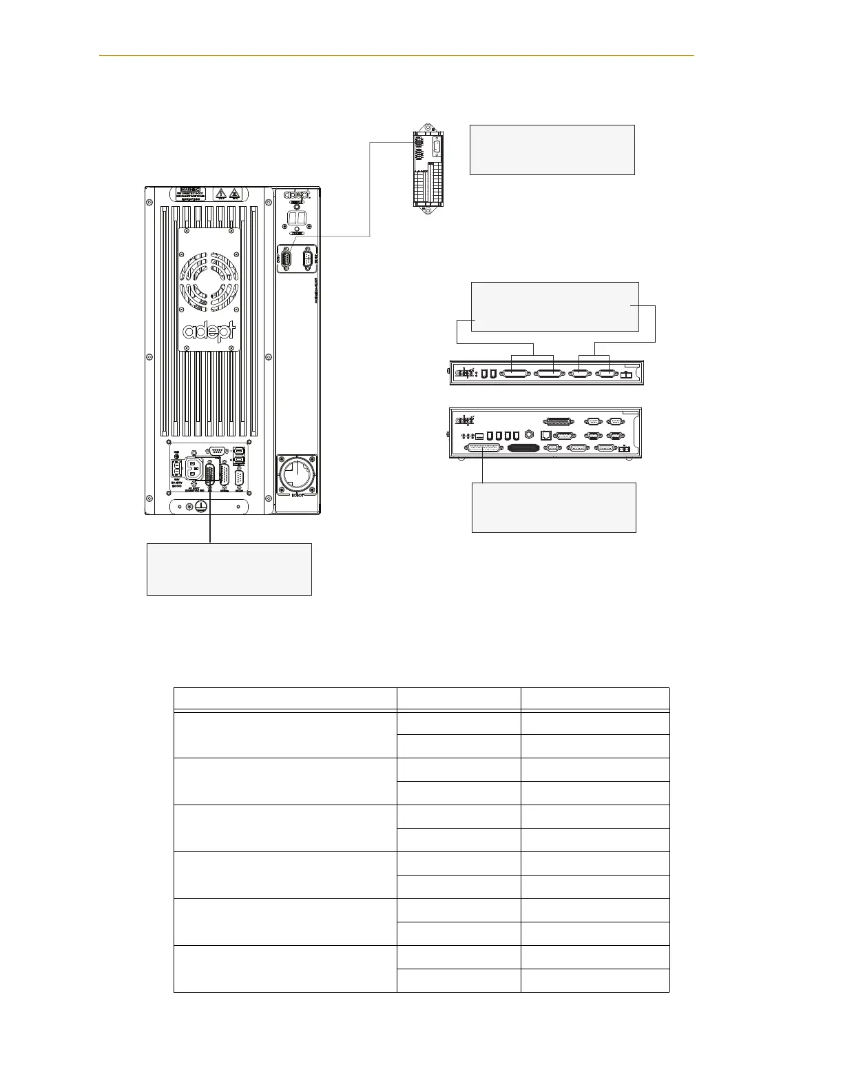
Figure 5-3. Connecting Digital I/O to the System
Table 5-2. Default Digital I/O Signal Configuration, Single Robot System
Location Type Signal Range
Controller XDIO connector Inputs 1001 - 1012
Outputs 0001 - 0008
sDIO Module 1 Inputs 1033 - 1064
Outputs 0033 - 0064
sDIO Module 2 Inputs 1065 - 1096
Outputs 0065 - 0096
sDIO Module 3
(recommended
a
)
Inputs 1201 - 1232
Outputs 0201 - 0232
sDIO Module 4
(recommended
a
)
Inputs 1233 - 1264
Outputs 0233 - 0264
IO Blox 1 Inputs 1113 - 1120
Outputs 0105 - 0112
SF
IEEE-1394
X2
SC-DIO
LINK
*S/N 3563-XXXXX*
X1
24V 0.5A
R
OK
X4
- + - +
1.1 1.2
XDC1 XDC2
X3
R
ON
SmartServo IEEE-1394
1 2 3 4
SF ES HD
SW1
1.1 1.2 2.1 2.2
OK
123
XDIO
LANHPE
OFF
XSYS
CAMERA
Eth 10/100
XUSR
Device Net
XFP
RS-232/TERM
RS-232-1
XMCP
BELT ENCODER
SmartController CX
-+ -+
RS-422/485
XDC1 XDC2
24V 5A
*S/N 3562-XXXXX*
RS-232-2
Optional
sDIO #1
SmartController
MB-60R
Optional
IO Blox Device
XIO Connector
12 Input signals: 1097 to 1108
8 Output signals: 0097 to 0104
XDIO Connector
12 Input signals: 1001 to 1012
8 Output signals: 0001 to 0008
IO Blox #1
8 Input signals: 1113 to 1120
8 Output signals: 0105 to 0112
sDIO #1
32 Input signals: 1033 to 1064
32 Output signals: 0033 to 0064