Chapter 2 - Robot Installation
32 Adept Viper s650/s850 Robot with MB-60R User’s Guide, Rev D
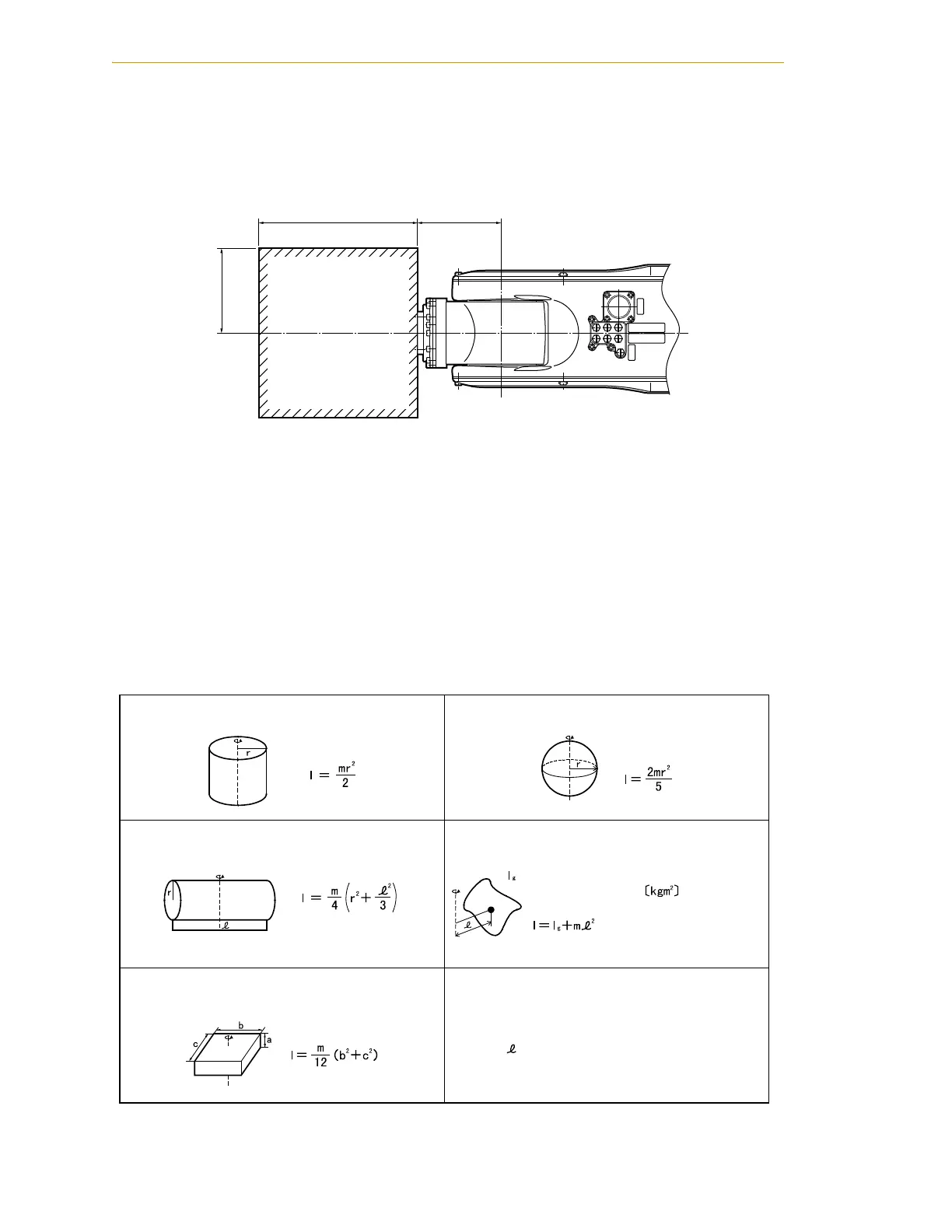
Center of Gravity Position of End-Effector
Design an end-effector so that the center of gravity position of the end-effector (including
workpiece) is within the range shown in the following figure.
Figure 2-9. Allowable Range of Center of Gravity Position of End-effector
Moment of Inertia Around J4, J5, and J6
Design an end-effector so that its moments of inertia around J4, J5, and J6 (including mass
of workpiece) do not exceed the maximum allowable moments of inertia of the robot.
• Maximum allowable moment of inertia around J4 and J5: 0.295 kgm
2
• Maximum allowable moment of inertia around J6: 0.045 kgm
2
When calculating the moment of inertia around J4, J5, and J6 of the end-effector, use the
formulas given in the following table, and see examples in Figure 2-10 on page 33.
Table 2-5. Moment of Inertia Formulas
1A
2A
3A
1B
2B
3B
AIR2
CN21
80150
80
1. Cylinder (1)
(Axis of rotation = Center axis)
4. Sphere
(Axis of rotation = Center axis)
2. Cylinder (2)
(The axis of rotation passes through the center of gravity.)
5. Center of gravity not on the axis of rotation
:
3. Rectangular parallelepiped
(The axis of rotation passes through the center of gravity.)
l: Moment of inertia ikgm
2
j
m: Mass ikgj
r: Radius imj
b, c, : Length imj
Inertia moment around center of gravity