Chapter 3 - MotionBlox-60R
36 Adept Viper s650/s850 Robot with MB-60R User’s Guide, Rev D
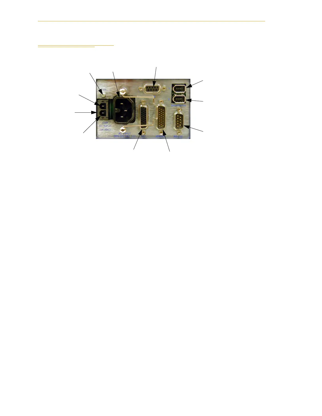
3.2 Description of Connectors on MB-60R Interface Panel
Figure 3-2. MB-60R Interface Panel
24 VDC - for connecting user-supplied 24 VDC power. The mating connector is provided.
Ground Point - for connecting cable shield from user-supplied 24 VDC cable.
200/240 VAC - for connecting 200-240 VAC, single-phase, input power. The mating
connector is provided.
XSLV - for connecting the supplied XSYS cable from the controller XSYS connector. (DB-9,
female).
SmartServo 1/2 - for connecting the IEEE 1394 cable from the controller (SmartServo 1.1)
to the upper connector (SmartServo 1).
RS-232 - Reserved for future use (DB-9, male).
XPANEL - Not used (DB-26, high density, male).
XIO - for user I/O signals for peripheral devices. This connector provides 8 outputs and
12 inputs. See Section 3.4 on page 40 for connector pin allocations for inputs and outputs.
That section also contains details on how to access these I/O signals via V+. (DB-26, high
density, female)
24 VDC
Input
200-240 VAC
Input
XSLV
XIO
XPANEL
RS-232
SmartServo Port 1
+24 V Pin
Ground
Point
SmartServo Port 2
Ground Point
for Cable Shield