Connecting 200-240 VAC Power to MB-60R
Adept Viper s650/s850 Robot with MB-60R User’s Guide, Rev D 59
equipment or transient suppressor shall be capable of absorbing the energy in the
transient.
In the industrial environment, nonperiodic over-voltage peaks may appear on mains
power supply lines as a result of power interruptions to high-energy equipment (such as a
blown fuse on one branch in a 3-phase system). This will cause high-current pulses at
relatively low voltage levels. The user shall take the necessary steps to prevent damage to
the robot system (such as by interposing a transformer). See
IEC 1131-4 for additional
information.
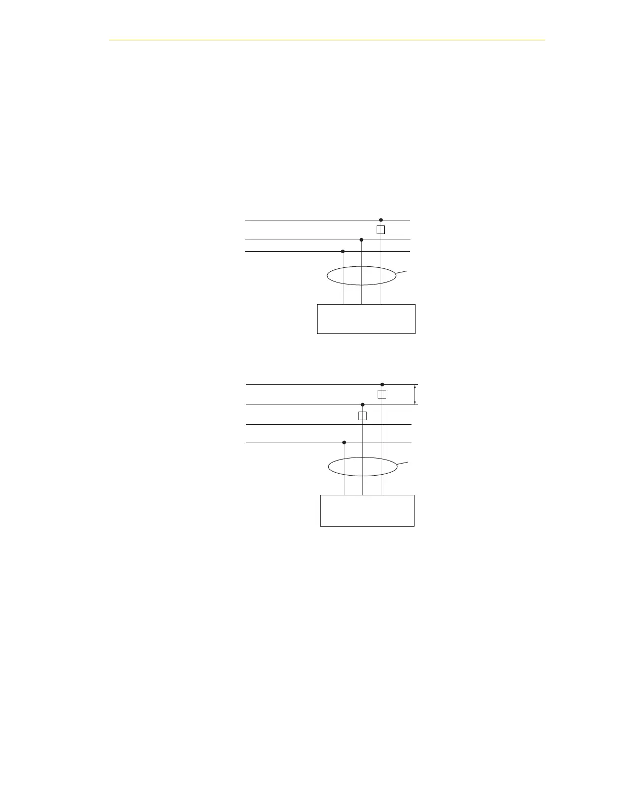
AC Power Diagrams
Figure 4-3. Typical AC Power Installation with Single-Phase Supply
Figure 4-4. Single-Phase Load across L1 and L2 of a Three-Phase Supply
Details for AC Mating Connector
The AC mating connector is supplied with each system. It is shipped in the
cable/accessories box. The supplied plug is internally labeled for the AC power
connections (L, E, N).
E
E
N
N
L
L
F1 10A
MB-60R
1Ø 200–240 VAC
User-Supplied
AC Power Cable
Note: F1 is user-supplied, must be slow blow.
1Ø
200–240 VAC
20A
L = Line
N = Neutral
E = Earth Ground
E
E
N
L3
L
L1
L2
F5 10A
F4 10A
MB-60R
1Ø 200–240 VAC
User-Supplied
AC Power Cable
Note: F4 and F5 are user-supplied, must be slow blow.
3Ø
200–240 VAC
L = Line 1
N = Line 2
E = Earth Ground
200–240 VAC