Chapter 1: Overview
15
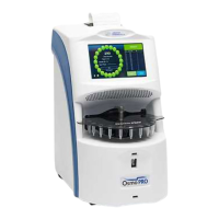
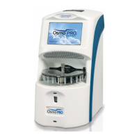
OsmoTECH PRO Multi-Sample Micro-Osmometer Service Guide
RS-232 driver circuits
The instrument uses three RS-232 ports that:
• Communicate to the display PCB
• Communicate to the scanner
• Communicate to the printer
A transceiver IC handles the level translation of all three
ports.
Osmometer module circuits
The osmometer circuits control three 12 VDC stepper
motors that rotate the turntable and engage/disengage
the cooling block with the sample probe. Three fans
expel air from the instrument, remove heat from the
TEC module, and expel warm air accumulating at the
top of the instrument.
Three optical sensors control the motor positions. Three
proximity sensors determine the presence of sample
tubes, motor positions, and turntable presence (either
ON or OFF).
Display assembly
The display assembly (p/n 222022) is the main user
interface controller and provides connectivity to the
USB and Ethernet peripherals. It contains the display
PCB and color LCD screen, resistive touch element, and
the USB/Ethernet extension cables. The assembly is
secured underneath the top of the instrument’s bezel
cover.
7” Color/touch LCD screen
The OsmoTECH PRO has a 7” WVGA (800 x 480)
LCD/touch screen built into the display assembly. It uses
a metal gasket to reduce radiated electrical emissions.
The LCD screen has a built-in four-wire resistive touch
screen overlay.
Display PCB
The display PCB contains a high-power IMX6 micro-
processor running a real-time operating system (RTOS)
from Mentor Graphics called Nucleus. The
microprocessor interacts with the color/touch LCD
screen and provides the following serial interfaces to
the control PCB:
• Two USB 2.0 type A ports
• One USB 2.0 type B port
• One Ethernet port
Interfaces
The display PCB has the following interfaces:
• RS-232 (1x): This serial interface communicates
commands and data to/from the control PCB.
• USB 2.0 Type A (2x): These interfaces allow a USB
device to be attached to the rear of the instrument
with internal shielded USB cable to USB adapter.
• USB 2.0 Type B (1x): This interface allows a USB
device to be attached to the rear of the instrument
with an internal shielded USB cable to USB adapter.
• Ethernet (1x): This interface allows a 10/100 RJ45
cable to attach to the rear of the instrument with an
internal shielded Ethernet cable to Ethernet adapter.
Non-volatile memory
The display PCB has non-volatile memory used to store
the last one thousand sample records.
The control PCB has non-volatile memory used to store
instrument set-up, calibration, and other pertinent data.
Real-time clock
The display PCB has a real-time clock and a back-up
battery to maintain the date, time, and firmware
versions.
 Loading...
