Chapter 1: Overview
14
OsmoTECH PRO Multi-Sample Micro-Osmometer Service Guide
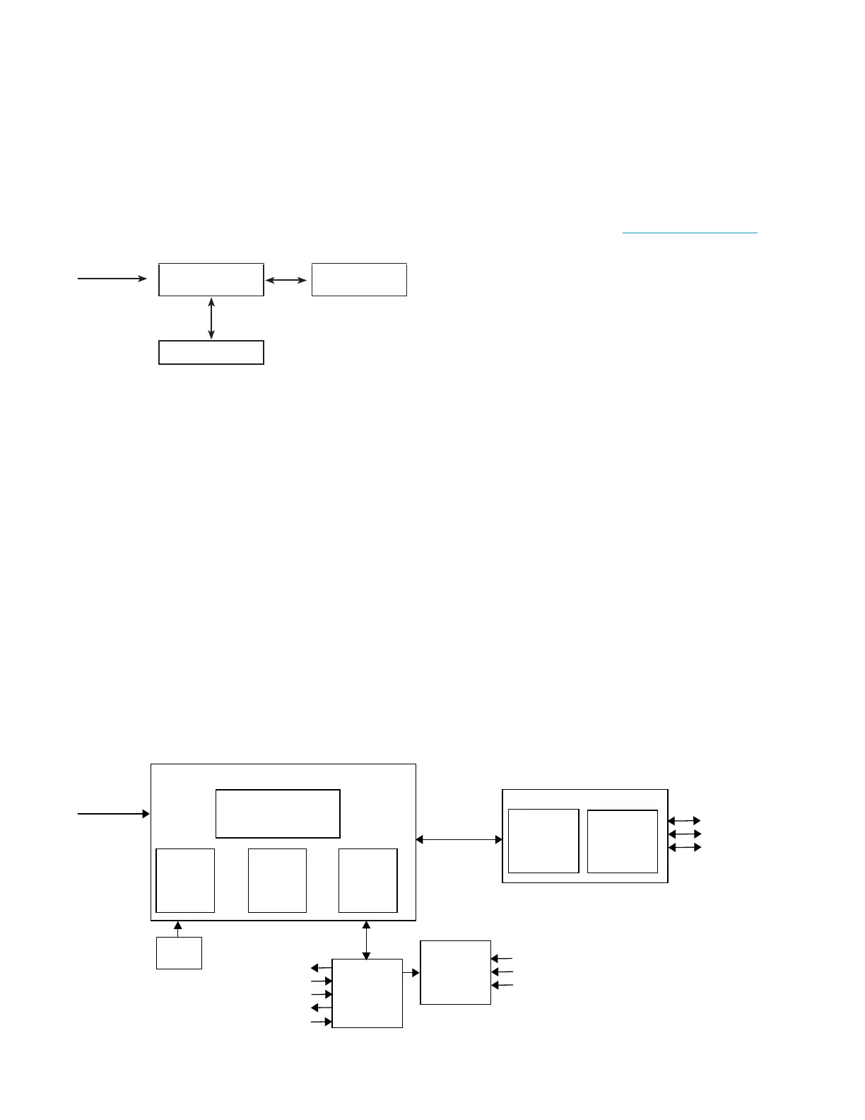
1.4 Mechanical description
Mechanically, the OsmoTECH PRO contains the three
major components shown in the diagram and listed
below.
110–240 VAC
50/60 Hz
Power supply and
controls assembly
Display assembly
Osmometer
module
• Osmometer module: This component is where the test
is performed. The sample probe, cooling assembly,
turntable, and motors are all components of the
osmometer module.
• Power supply and controls assembly: This component
provides power to the instrument via the fused power
inlet assembly. The control PCB contains the logic to
perform osmometer tests and manage
communications with the display assembly and
barcode scanner. The USB and Ethernet ports are
mounted to the power supply and controls assembly,
and are connected to the display assembly.
• Display assembly: This assembly consists of the
display PCB and the touchscreen display. It provides
the graphical user interface (GUI) used to show and
retrieve information about tests and the instrument
settings. The USB and Ethernet port interfaces and
cables are part of the display assembly.
AC/DC
power
supply
Exhaust
fans
Control
PCB
Power entry module
(switch, fused, filtered)
Barcode
scanner
Power/control box
110 V/220 V
power in
Serial
Display box
Color/touch
display
Sample
cooling
assembly
Display
PCB
Osmometer
module
3- Stepper motors
3 - Motor home sensors
3 - Proximity sensors
2 - Cooling fans
1 - Temperature/humidity sensor
2 - USB A ports
1 - USB B port
1 - Ethernet port
2 - Temperature probes (24 bit)
1 - TEC cooler
1 - Solenoid impactor
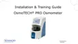
1.5 Electrical description
This section describes the major electrical components
in the OsmoTECH PRO (see Mechanical description).
Electrically, the OsmoTECH PRO contains the
components shown in the diagram and described next.
Power supply and control PCB assembly
The power supply and control PCB assembly
(p/n222028) are divided into lower and upper sections
by a metal shelf.
• The lower section contains the power entry module
(PEM), a 200W AC/DC power supply, and a fan. All
high-voltage connections are contained in the lower
section, making it safe to operate the instrument with
the rear cover removed.
• The upper section contains the control PCB
(p/n222037PC). This board controls all of the
instrument’s low-level, time-sensitive operations, such
as the thermo-electric chamber, solenoid, barcode
scanner, and high-precision temperature probes. The
control board uses the PIC32MZ microchip micro-
controller.
Barcode scanner port
This port communicates to a 2D barcode scanner
(Diamond Technologies DSE0450-DTC0E) with a
115Kbps, 1start bit, 1 stop bit, and no parity protocol. The
scanner’s presentation mode activates when an object
trips the scanner proximity sensor. The sensor has
built-in white LEDs to help read barcodes in low light
conditions.