R3131 Spectrum Analyzer Operation Manual
2.2.11 Harmonic Distortion
Setting the measurement conditions
This changes the analyzer settings so that the input signal is displayed more clearly.
5. Press FREQ, 3, 0, 0 and MHz.
A center frequency of 300 MHz is set.
6. Press SPAN, 5, 0, 0 and MHz.
A frequency span of 500 MHz is set.
7. Press BW, RBW A LITO/MNL, 1, 0 and kHz.
The RBW is set to 10 kHz.
Verifying harmonic distortion
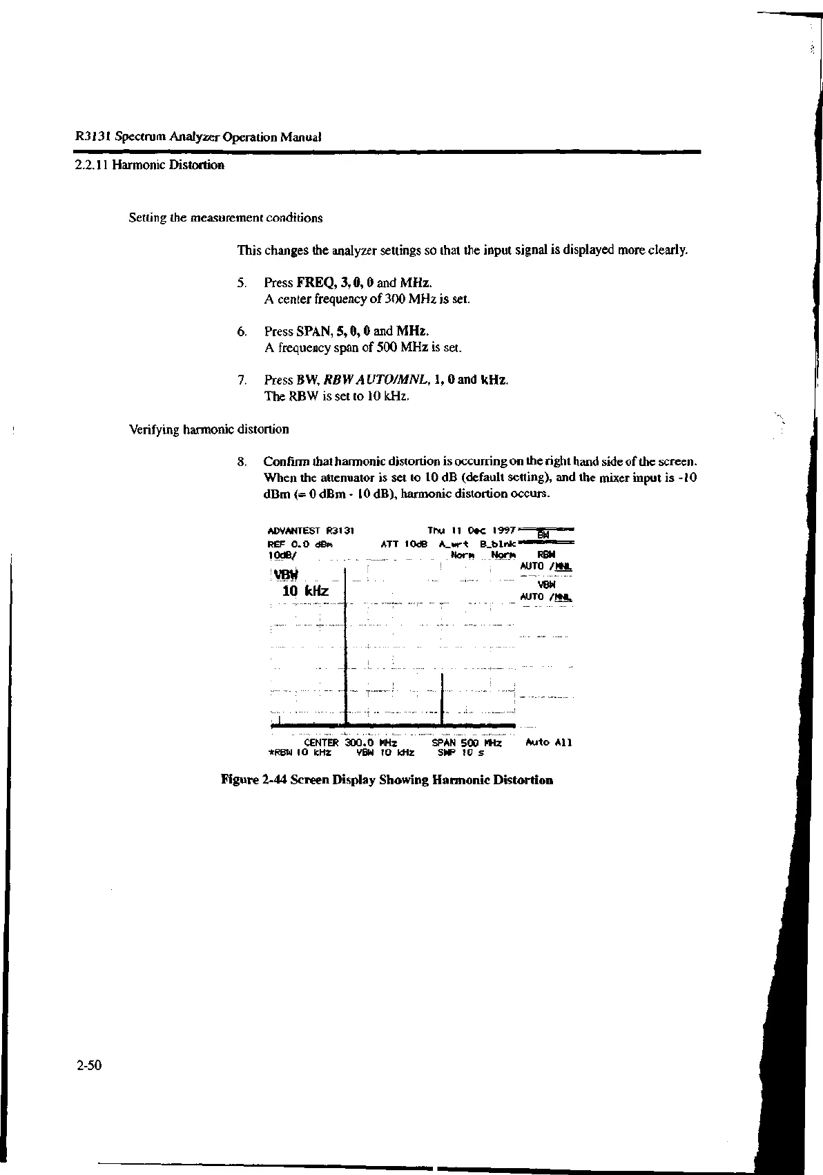
8. Confirm that harmonic distortion is occurring on the right hand side of the screen.
When the attenuator is set to 10 dB (default setting), and the mixer input is -10
dBm 0 dBm - 10 dB), harmonic distortion occurs.
ADVANTEST R3131
REF 0.0 dBm
10dB/
VBW
10 kHz
Thu 11 Dec 1997
ATT 10dB A_wrt B_blnk
Norm Norm RBW
AUTO /MNL
VBW
AUTO /MNL
CENTER 300.0 MHz
*RBW 10 kHz VBW 10 kHz
BW
SPAN 500 MHz Auto All
SWP 10 s
Figure 2-44 Screen Display Showing Harmonic Distortion
2-50
 Loading...

