R3131 Spectrum Analyzer Operation Manual
oterxig =
=,...000.,
000 0 So
0 0.0....nae• 0
g
SS 000p0
r
0 0 0
411)-
00
0 .00 0
0O .1
0 0 10
00 0
0000
1.10
00 0
v• 000 0
1=1=1
10.01:1
cool
3remom.
Power combiner
CI
00
O
10
000 0
1200 0
O
11
0
(Insertion loss: 6 dB)
C.
0.0
0
000 0
1000 1.1
0
?OUTPUT
2.2.12 Intermodulation
2.2.12 Intermodulation
This section describes how to set up the attenuator (ATT) when using a spectrum analyzer which is receiv-
ing more than one input signal.
When signals with an excess amplitude are input, spurious signals produced by intermodulation are dis-
played. It is important that the ATT be adjusted to moderate the mixer input.
Setup
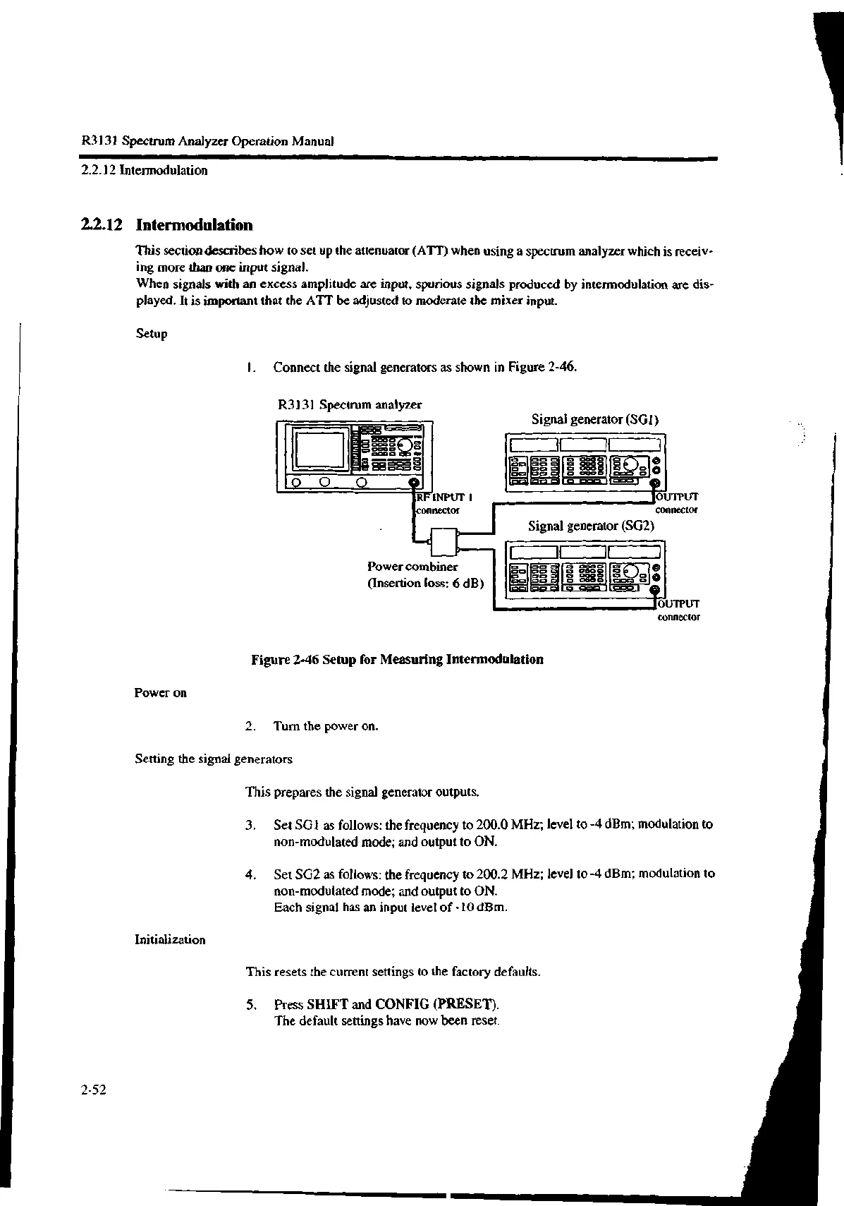
1. Connect the signal generators as shown in Figure 2-46.
R3131 Spectrum analyzer
connector I connector
Signal generator (SG2)
Signal generator (SG1)
"OUTPUT
Figure 2-46 Setup for Measuring Intermodulation
Power on
2. Turn the power on.
Setting the signal generators
This prepares the signal generator outputs.
Initialization
2-52
connector
3. Set SGI as follows: the frequency to 200.0 MHz; level to -4 dBm; modulation to
non-modulated mode; and output to ON.
4. Set SG2 as follows: the frequency to 200.2 MHz; level to -4 dBm; modulation to
non-modulated mode; and output to ON.
Each signal has an input level of -10 dBm.
This resets the current settings to the factory defaults.
5. Press SHIFT and CONFIG (PRESET).
The default settings have now been reset.

 Loading...
