R3131 Spectrum Analyzer Operation Manual
1701=1c3.2.
g=1 000 0
= 000 0 4 I.1= 000 0 =
01
000 0 Q ...
. ..... _ =
. = 00
2.3.7 Measurements Using TO (Option 74)
Connecting the unit under test
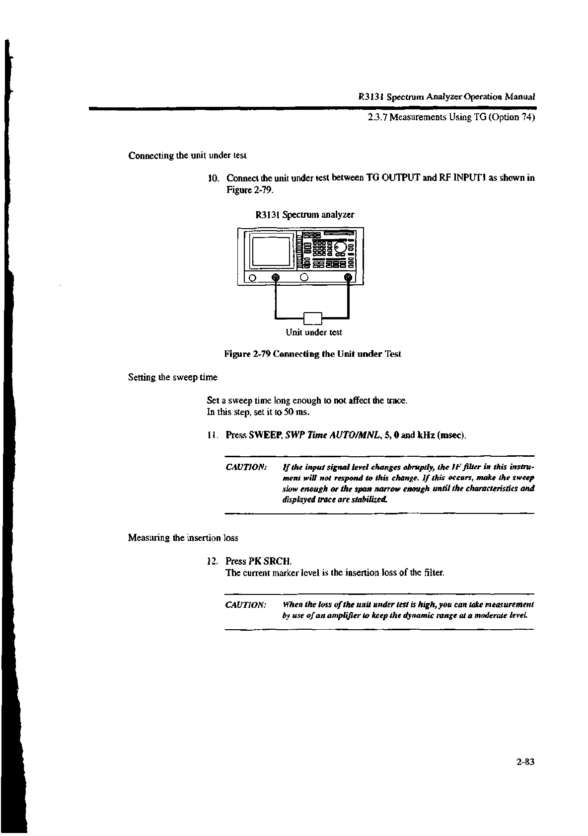
10. Connect the unit under test between TG OUTPUT and RF INTPUT1 as shown in
Figure 2-79.
R3131 Spectrum analyzer
Unit under test
Figure 2-79 Connecting the Unit under Test
Setting the sweep time
Set a sweep time long enough to not affect the trace.
In this step, set it to 50 ms.
11. Press SWEEP, SWP Time AUTO/MNL, 5, 0 and kHz (msec).
CAUTION: If the input signal level changes abruptly, the IF filter in this instru-
ment will not respond to this change. If this occurs, make the sweep
slow enough or the span narrow enough until the characteristics and
displayed trace are stabilized.
Measuring the insertion loss
12. Press PK SRCH.
The current marker level is the insertion loss of the filter.
CAUTION: When the loss of the unit under test is high, you can take measurement
by use of an amplifier to keep the dynamic range at a moderate level.
2-83

 Loading...
