R3131 Spectrum Analyzer Operation Manual
4
ms
g.....Q:si
r,
.„......
.... —
. --.
00 0010 0
00101000
0 0 0
9-
..
00
10
00
........
0C:1 0
00
00 0
0 000 0
0 000 0
0 000 0
..c
0
01
000 0
0
o
9
I
0
00
0
00
00 0
00
00 0
001 0
0 noon
0 000 0Cl
0 000 0
0 00010
0 0
...g. 0 es,
r --r.-1
- - -
-L, ...... I
_.'e'=r=r9
2.2.8 Separating Two Signals
2.2.8 Separating Two Signals
This section describes how RBW should be set to properly observe adjacent signals using the spectrum
analyzer.
Setup
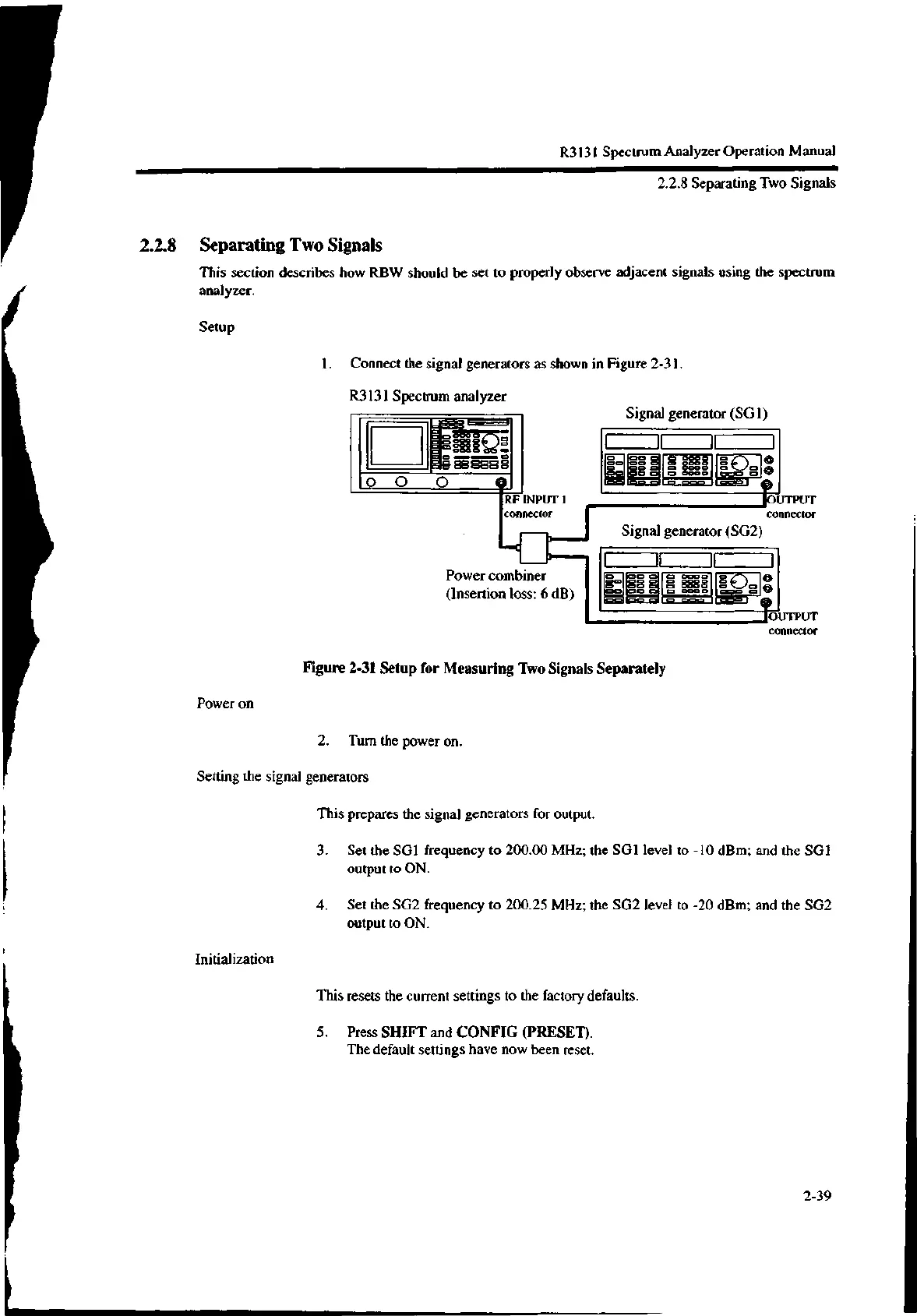
1. Connect the signal generators as shown in Figure 2-31.
R3131 Spectrum analyzer
RF INPUT I
connector
Signal generator (SG1)
Power combiner
(Insertion loss: 6 dB)
Signal generator (SG2)
•UTPUT
connector
Figure 2-31 Setup for Measuring Two Signals Separately
Power on
2. Turn the power on.
Setting the signal generators
This prepares the signal generators for output.
Initialization
OUTPUT
connector
3. Set the SG1 frequency to 200.00 MHz; the SG1 level to -10 dBm; and the SG1
output to ON.
4. Set the SG2 frequency to 200.25 MHz; the SG2 level to -20 dBm; and the SG2
output to ON.
This resets the current settings to the factory defaults.
5. Press SHIFT and CONFIG (PRESET).
The default settings have now been reset.
2-39

 Loading...
