R3131 Spectrum Analyzer Operation Manual
EEISQg
r0
—.... .=.
,........_.
M MS S
0 0 0 CP--
I I
CI
cm=
CI
00
0 CI
e e e
0 CI
00
- -
0 000o
e 0000
0 0 00 0
0 0000
0
I -F,M==71 - - 9
2.2.11 Harmonic Distortion
2.2.11 Harmonic Distortion
Harmonic distortion is produced by non-linearity from the input mixer if the input exceeds a certain limit.
As a result, spurious signals which do not come from the input signal may be observed.
Setup
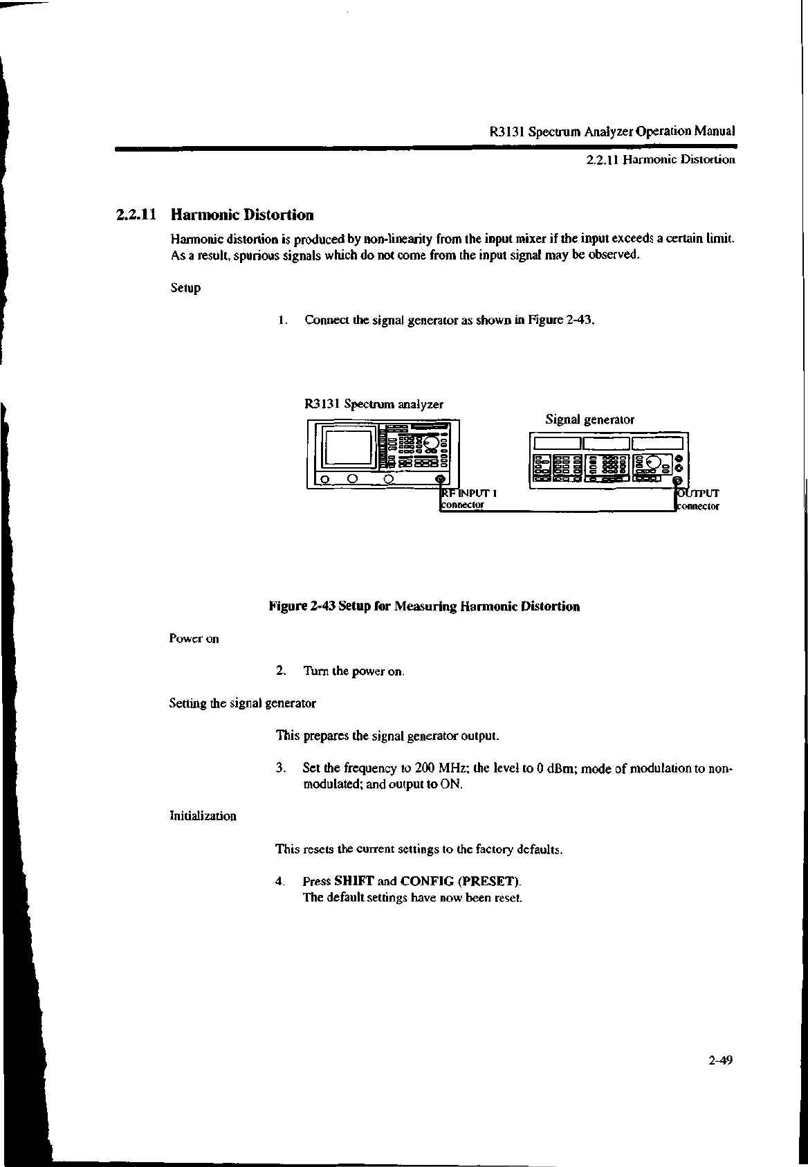
1. Connect the signal generator as shown in Figure 2-43.
R3131 Spectrum analyzer
NPUT 1
'connector
Signal generator
Figure 2-43 Setup for Measuring Harmonic Distortion
Power on
2. Turn the power on.
Setting the signal generator
This prepares the signal generator output.
Initialization
UTPUT
'connector
3. Set the frequency to 200 MHz; the level to 0 dBm; mode of modulation to non-
modulated; and output to ON.
This resets the current settings to the factory defaults.
4. Press SHIFT and CONFIG (PRESET).
The default settings have now been reset.
2-49

 Loading...
