R3I31 Spectrum Analyzer Operation Manual
,4110111/4"01111110/80
3000 MHz
SWP 50 ms
Corr Mode
ANT /LVL
CENTER 1.5000 8Hz SPAN
RBW 1 MHz VBW 1 MHz
CCRRECTION FACTOR
1:
500.000000 MHz
-45.00 dB
2:
800.000000 MHz
-35.00 dB
3:
1000.000000 MHz
-15.00 dB
4:
1200.000000 MHz
-5.00 dB
.. _
5:
1400.000000 MHz
0.00 dB
Clear
6:
Table
7:
8:
9:
to:
2.3 Measurement Examples
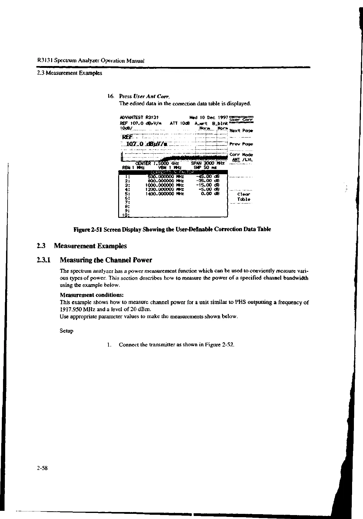
16. Press User Ant Corr.
The edited data in the correction data table is displayed.
ADVANTEST R3131
REF 107.0 dBpV/m
194$/__
REF-
Wed 10 Dec 1997 User Corr
ATT 10dB A_wrt
Norm "9" Next Page
Prey Page
Figure 2-51 Screen Display Showing the User-Definable Correction Data Table
2.3 Measurement Examples
2.3.1 Measuring the Channel Power
The spectrum analyzer has a power measurement function which can be used to conviently measure vari-
ous types of power. This section describes how to measure the power of a specified channel bandwidth
using the example below.
Measurement conditions:
This example shows how to measure channel power for a unit similar to PHS outputting a frequency of
1917.950 MHz and a level of 20 dBm.
Use appropriate parameter values to make the measurements shown below.
Setup
2-58
1. Connect the transmitter as shown in Figure 2-52.

 Loading...
