R3131 Spectrum Analyzer Operation Manual
mmor=es
=10
= 000 0
= 000 0 0
= 000 0 0
000 0 0 ,=.
0 •=s = 0
.M.• 00 000 0
0
o 0 0
2.3.7 Measurements Using TG (Option 74)
2.3.7 Measurements Using TG (Option 74)
Band-pass filter characteristics with a passband of approximately 270 MHz, are measured (both the inser-
tion loss and bandwidth are measured).
CAUTION: UNCAL messages, displayed when measuring frequency characteristics using this function, do not
affect measurement results.
Setup
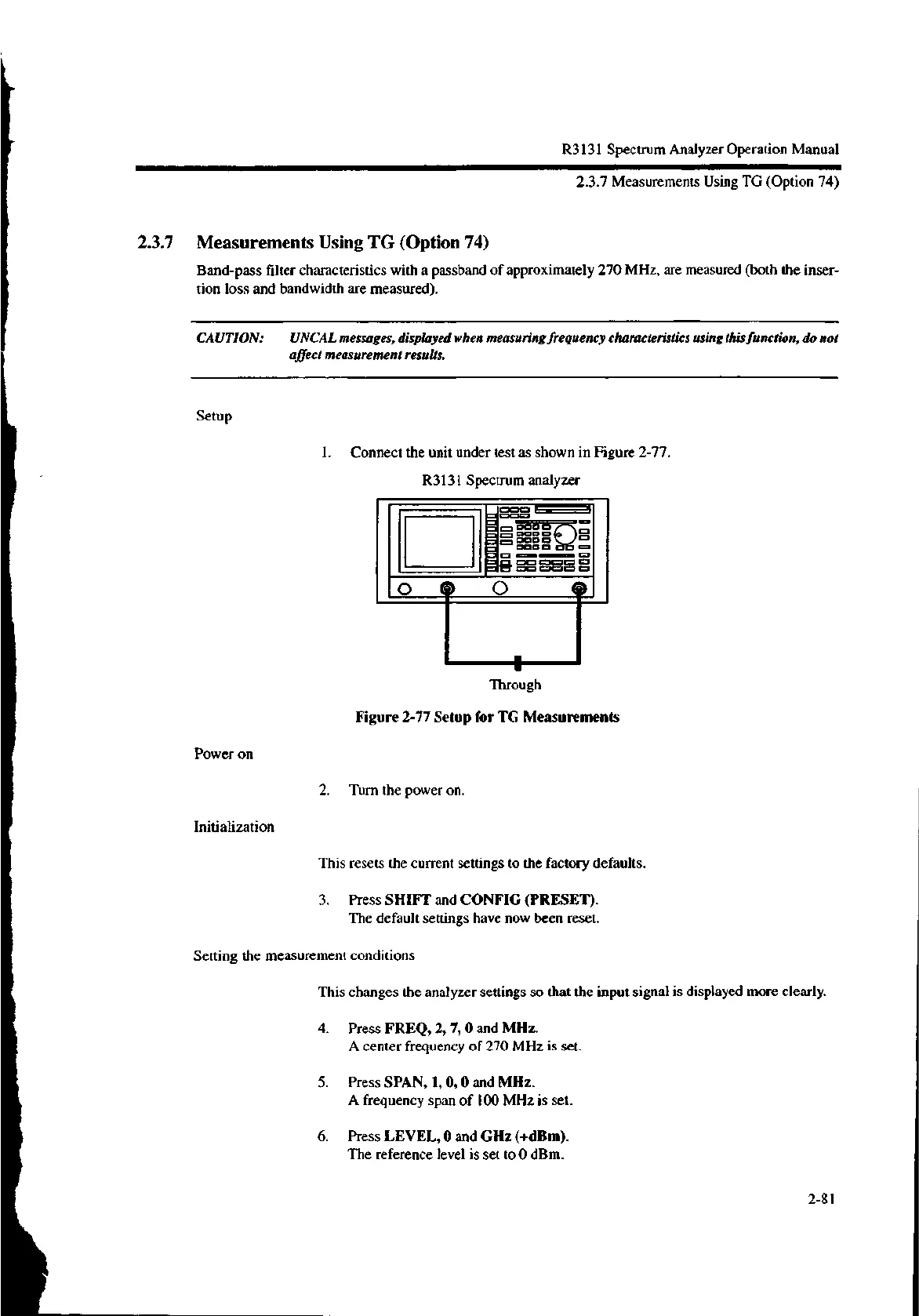
1. Connect the unit under test as shown in Figure 2-77.
R3131 Spectrum analyzer
.--- I
Through
Figure 2-77 Setup for TG Measurements
2. Turn the power on.
This resets the current settings to the factory defaults.
3. Press SHIFT and CONFIG (PRESET).
The default settings have now been reset.
Setting the measurement conditions
This changes the analyzer settings so that the input signal is displayed more clearly.
4. Press FREQ, 2, 7, 0 and MHz.
A center frequency of 270 MHz is set.
5. Press SPAN, 1, 0, 0 and MHz.
A frequency span of 100 MHz is set.
6. Press LEVEL, 0 and GHz (+dBm).
The reference level is set to 0 dBm.
Power on
Initialization
2-81

 Loading...
