R3131 Spectrum Analyzer Operation Manual
4.2 RS-232 Remote Control Function
4.2.4 Interface connection
Spectrum Analyzer rear panel Personal computer
if
o 0
0 0 0
I
im.1111EN
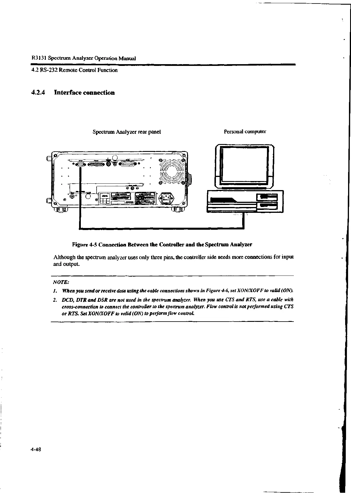
Figure 4-5 Connection Between the Controller and the Spectrum Analyzer
Although the spectrum analyzer uses only three pins, the controller side needs more connections for input
and output.
NOTE:
1. When you send or receive data using the cable connections shown in Figure 4-6, set XON/XOFF to valid (ON).
2. DCD, DTR and DSR are not used in the spectrum analyzer. When you use CTS and RTS, use a cable with
cross-connection to connect the controller to the spectrum analyzer. Flow control is not performed using CTS
or RTS. Set XON/XOFF to valid (ON) to perform, low control.
4-48

 Loading...
