R3131 Spectrum Analyzer Operation Manual
.=1 000 0 C)=.
=. 000 0
CI00 0 N- l P
r,
000 0 ab 4=.
0
0 .m....e
00 0010 0
00 000 0
0 0 0
9-
00
S 0000
O
00
0 000 0
0 000 0
2.2.10 Input Saturation
2.2.10 Input Saturation
After a signal being sent to the input mixer reaches a certain level, the displayed value is not proportional
to the signal input because of saturation. An input level producing a I db error due to saturation is defined
as the gain compression. In this example, you apply two input signals and verify that an input signal whose
value is less than the limit of gain compression produces less output than it would under perfect linearity.
This phenomenon is caused by another input signal whose value is larger than the gain compression limit.
Setup
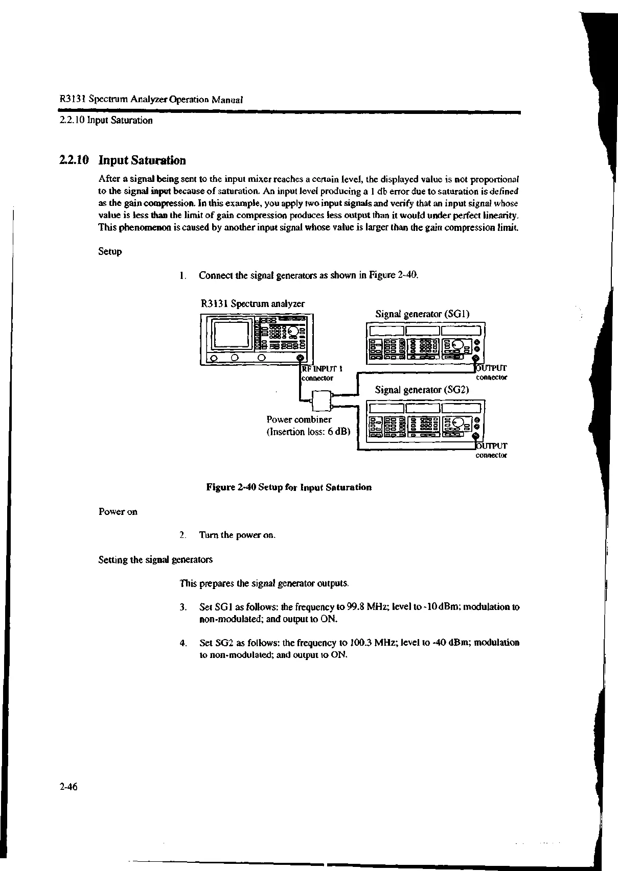
1. Connect the signal generators as shown in Figure 2-40.
R3131 Spectrum analyzer
RF INPUT I
connector
Signal generator (SG1)
Power combiner
(Insertion loss: 6 dB)
Figure 2-40 Setup for Input Saturation
Power on
2. Turn the power on.
Setting the signal generators
This prepares the signal generator outputs.
Signal generator (SG2)
tUTPUT
connector
tUTPUT
connector
3. Set 501 as follows: the frequency to 99.8 MHz; level to -10 dBm; modulation to
non-modulated; and output to ON.
4. Set SG2 as follows: the frequency to 100.3 MHz; level to -40 dBm; modulation
to non-modulated; and output to ON.
2-46
1

 Loading...
