Device State Register Set
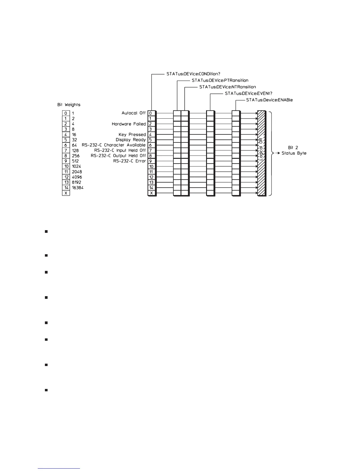
The Device State register set monitors the states of eight device-specific parameters. See figure 1-7.
Bits in the Device State condition register are set to 1 under the following conditions:
Autocal Off (bit 0) is set to 1 when the analyzer’s autocalibration function is disabled (CAL:AUTO
OFF).
Hardware Failed (bit 2) is set to 1 when the analyzer detects a failure in its own hardware.
Key Pressed (bit 4) is set to 1 when one of the front panel keys is pressed. This is an event. The
condition register will always return 0 for this bit.
Display Ready (bit 5) is set to 1 when measurement results are available. This is an event. The
condition register will always return 0 for this bit.
RS-232-C Character Available (bit 6) is set to 1 when a character is in the input buffer.
RS-232-C Input Held Off (bit 7) is set to 1 when input is held off due to handshake protocol
conditions.
RS-232-C Output Held Off (bit 8) is set to 1 when output is held off due to handshake protocol
conditions.
RS-232-C Error (bit 9) is set to 1 when a framing error, overrun error, parity error, or break is
detected.
Figure 1-7 also shows the commands you use to read and write the Device State registers. See chapter 20
for more information about these commands.
The Agilent 35670A’s Status Registers
1-16
1-7. The Device State Register Set

 Loading...


