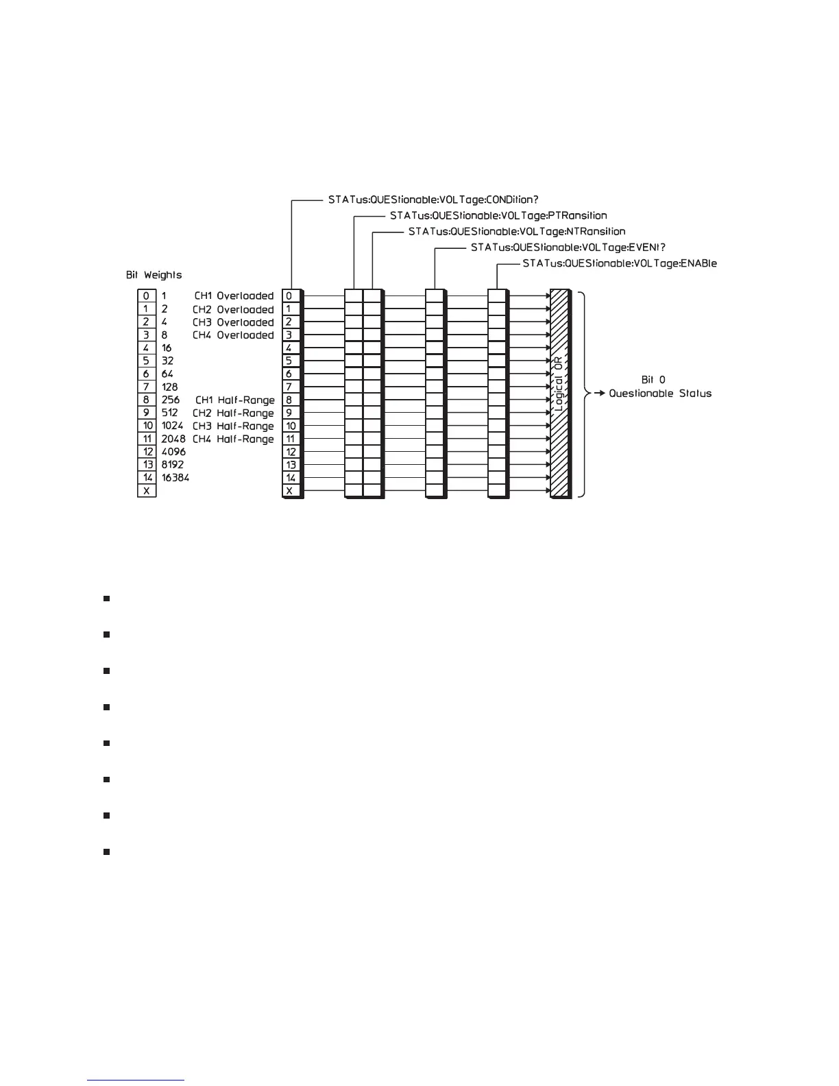
Questionable Voltage Register Set
The Questionable Voltage register set monitors conditions that affect the amplitude accuracy of
measurement data. See figure 1-10.
Bits in the Questionable Voltage condition register are set to 1 under the following conditions:
Channel 1 Overload (bit 0) is set to 1 when any input signal exceeds the current channel 1 input
range.
Channel 2 Overload (bit 1) is set to 1 when any input signal exceeds the current channel 2 input
range.
Channel 3 Overload (bit 2) in Option AY6 only is set to 1 when any input signal exceeds the current
channel 3 input range.
Channel 4 Overload (bit 3) in Option AY6 only is set to 1 when any input signal exceeds the current
channel 4 input range.
Channel 1 Input Half-Range (bit 8) is set to 1 when any input signal is larger than half the current
channel 1 input range.
Channel 2 Input Half-Range (bit 9) is set to 1 when any input signal is larger than half the current
channel 2 input range.
Channel 3 Input Half-Range (bit 10) in Option AY6 only, is set to 1 when any input signal is larger
than half the current channel 3 input range.
Channel 4 Input Half-Range (bit 11) in Option AY6 only, is set to 1 when any input signal is larger
than half the current channel 4 input range.
Figure 1-10 also shows the commands you use to read and write the Questionable Voltage registers. See
chapter 20 for more information about these commands.
The Agilent 35670A’s Status Registers
1-19
1-10. The Questionable Voltage Register Set

 Loading...


