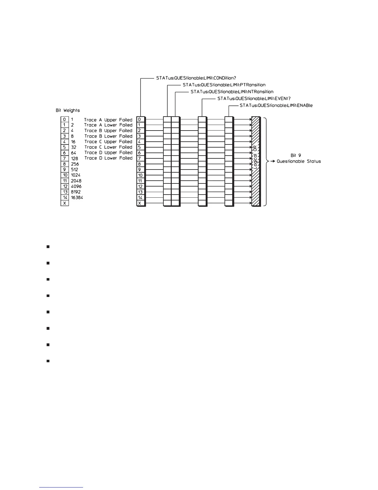
Limit Fail Register Set
The Limit Fail register set monitors limit test results for all traces. See figure 1-8.
Bits in the Limit Fail condition register are set to 1 under the following conditions:
Trace A Upper Failed (bit 0) is set to 1 when limit testing is enabled and any point on trace A
exceeds its upper limit.
Trace A Lower Failed (bit 1) is set to 1 when limit testing is enabled and any point on trace A falls
below its lower limit.
Trace B Upper Failed (bit 2) is set to 1 when limit testing is enabled and any point on trace B exceeds
its upper limit.
Trace B Lower Failed (bit 3) is set to 1 when limit testing is enabled and any point on trace B falls
below its lower limit.
Trace C Upper Failed (bit 4) is set to 1 when limit testing is enabled and any point on trace C exceeds
its upper limit.
Trace C Lower Failed (bit 5) is set to 1 when limit testing is enabled and any point on trace C falls
below its lower limit.
Trace D Upper Failed (bit 6) is set to 1 when limit testing is enabled and any point on trace D
exceeds its upper limit.
Trace D Lower Failed (bit 7) is set to 1 when limit testing is enabled and any point on trace D falls
below its lower limit.
Figure 1-8 also shows the commands you use to read and write the Limit Fail registers. See chapter 20
for more information about these commands.
The Agilent 35670A’s Status Registers
1-17
1-8. The Limit Fail Register Set

 Loading...


